Hello everyone,
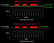
I am building a small guitar valve amplifier (this will matter later), and I will include a power attenuator. I have dedicated a heatsink to the attenuator part, and my question is whether there will be a significant difference in thermal spreading if I attach the power resistors directly on the heatsink (cutting a large chassis area off) or if was to leave the chassis sit in between.
I attach a detailed plan of the two placements. The chassis is made of 2mm AlMg3 (Aluminum 5754) and its total dimensions are 490 x 200 x 65mm. Since the amp is a guitar combo, all valves (and the heatsink) will be facing downwards - thus, I expect the chassis to get a bit warm or hot, regardless of the attenuator usage. The heatsink is bare aluminum, having a theoretical thermal resistance of about 1 C/W.
Correct me if I'm wrong: I assume that in the case of leaving the chassis sandwiched between heatsink and resistors, I will get a poorer thermal transfer to the heatsink, but "gain" a bit thermal spreading on the chassis. Whereas on the other case, thermal spreading to the chassis will be minimum, and transfer to the heatsink maximum. Do you think that the two solutions will differ significantly in:
(1) steady state resistor temperature
(2) steady state chassis temperature?
I understand that usually, you mount everything directly to the heatsink, but I was wondering if this could really make a difference here. Also, is there a way of calculating the thermal resistance values for the application? I tried some online calculators but got very different results.
Thanks!
Attachments
Convection is hard to model well, conduction in the heatsink is simple by comparison. Here the convection is important so I'd suggest experimentation is simpler than trying to model accurately something with a mix of air convection and metal conduction.
Well experimentation is always best, but this would require cutting off a chassis area, which is irreversible! 😛
My plan was not to cut the chassis at first - but again, assembling the amp and then deciding that the best solution was to cut the chassis to get directly to the heatsink, is practically impossible to implement.
I have given it some thought and I believe I must decide based on theory.. The difference could be slight, but hey, this is what a scientific discussion is all about - learning and planning based on what seems right at first.
The problem is not the heat transfer from the amp to the heatsink, but as Mark alluded to, the heat transfer from the heatsink to ambient.
Putting the heatsink upside down underneath the amp is the very worst you can do.
Second best is on top, best is sideways a bit elevated so that you have some air flow through the fins of the sink.
I do not know your reasons why you want it the way you showed it but from a heat management point of view you can't do worse.
You should be ready to at least double the heatsink or maybe more to give the amp a fighting chance to survive.
Jan
I am well aware that this is the worst orientation - this was the only option for me layout-wise, as I said this is a guitar combo amp with certain compromises.
I understand that deciding the best between two bad solutions might not be optimal compared to planning the best solution in the first place, but this is what triggered my question.. I always overengineer things, but hey, sometimes it's ok to not go for it. This is actually the experimentation part for me.
Still, would this mean that maybe spreading the heat across the whole chassis would help better than rely on the heatsink alone? Or maybe this would mean the chassis could become untouchable compared to the heatsink solution?
Adding the chassis as a heatsink will certainly help.
Unless it gets so hot that you can't play anymore.
Hard to say in advance.
BTW What is the purpose of those power resistors? Surely there must be a smart way around that?
Jan
Unless it gets so hot that you can't play anymore.
Hard to say in advance.
BTW What is the purpose of those power resistors? Surely there must be a smart way around that?
Jan
It is used as a power attenuator - let me explain this a bit in case you are not familiar with the concept. Meaning why crazy guitarists would need such a thing. 😛
In guitar amps, we often like the sound of an output valve stage being overdriven. But doing so, the speaker sound levels (guitar speakers are extremely sensitive) become huge, especially for a home/bedroom application. So, most of the times, the best approach is to add a power-sucking stage before the speaker to overdrive the output stage, but reduce the speaker volume dramatically.
Additionally, it is better to make the sucking stage's impedance look like a speaker so the output valves see a similar load to a speaker, but in any case this means a 1mH coil plus a network of power resistors.
My amp will have a 2xEL84 output stage, 335 B+, and a 6600 primary OT impedance. The transformer is a vintage Philips one, rated at 15W in theory.
So I would not expect significantly more power than 15W to be wasted on these power resistors, for the most extreme scenario of delivering only a tiny bit of power to the speaker, for a bedroom level instance.
This is a first-time build for me (the attenuator), just to try if it works as it "should", thus preserving a lot of an overdriven amp tone at bedroom levels.
So, you suggest that I try to go as planned (using the chassis along with the heatsink), but maybe go for a bigger heatsink already? I did not manage to calculate an accurate conduction for this: how much worse the heat transfer to the heatsink becomes because of the chassis in the middle.
To summarize it in a few words.Adding the chassis as a heatsink will certainly help.
Unless it gets so hot that you can't play anymore.
Hard to say in advance.
BTW What is the purpose of those power resistors? Surely there must be a smart way around that?
Jan
In guitar amps some people like the sound of an overdriven output stage.
But they don't want so much output power since it will be to loud.
So it's nothing more than just a power attenuator, to give the sound characteristics from the output stage but at much lower sound pressure levels.
@audiostrat I was just about to ask what output power we are talking about, but you just replied.
You can never waste MORE power. The question remains how much you want to attenuate?
For example, you could just go for half (7.5W) and also put the output tubes in triode mode.
Although in triode mode it will sound a tiny bit differently.
Also keep in mind that this is very rarely 15W continues.
So although the dynamic peaks could be a lot higher, the average output power would be probably a lot less.
Unless you play extremely fast very compressed metal non-stop. 😉 😀 😀
Maybe you can show a picture of your current cabinet, because at this point it's a little hard to understand the whole context?
Thanks for the answer! Exactly, the reason why I did not put much effort on this was that it is quite unlikely that 15W will be dissipated constantly.
I will not use the output valves as triodes, but I will include a switch for ultra linear operation.
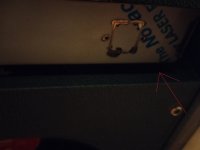
I attach two pictures (the amp is not assembled yet) - one of the back of the amp, and a small detail on the gap that the chassis will have from its back wood panel. The red arrow shows the approximate location of the heatsink - outside and underneath the chassis, close to the edge.
It is a quite typical combo guitar amp arrangement - I am not sure I have properly answered your question, if not tell me what more I can send.
Everything goes downwards, so heat is always a bigger problem.
I will not use the output valves as triodes, but I will include a switch for ultra linear operation.
I attach two pictures (the amp is not assembled yet) - one of the back of the amp, and a small detail on the gap that the chassis will have from its back wood panel. The red arrow shows the approximate location of the heatsink - outside and underneath the chassis, close to the edge.
It is a quite typical combo guitar amp arrangement - I am not sure I have properly answered your question, if not tell me what more I can send.
Everything goes downwards, so heat is always a bigger problem.
Attachments

Mount the heat sources directly to the heatsink. Unless both surfaces of the chassis are mirror-finish, perfectly flat, you'll be adding thermal resistance.

If chassis is aluminum it won't hurt and in fact help heatsink.
Horizontal heatsink is the worst but the real point is: will it be enough?
I guess it is.
Horizontal aluminum chassis have been used as heatsinks since forever in guitar amps .
Is it "the best"?
No.
Is it available and "enough"?
You bet.
Horizontal heatsink is the worst but the real point is: will it be enough?
I guess it is.
Horizontal aluminum chassis have been used as heatsinks since forever in guitar amps .
Is it "the best"?
No.
Is it available and "enough"?
You bet.
How about a cooling tunnel and a Noctua fan? Get a 120 mm one. They're dead quiet (<10 dB(A) SPL).
Tom
Tom
Unless I missed it you didn't say what type and how many power resistors you are using, so nobody can really answer your question. Other than that, just theremal grease the heatsink to the chassis and mount the (supposedly chassis mount) resistors to the chassis with grease also. don't use silicone pads unless you Have to. I'm assuming the chassis is yet uncoated, but unless powder coated that probably won't even matter here. Get 30-50 watts worth of resistors (they're cheap) and nothing will ever go wrong. If you don't believe me, get two of those heatsinks too.
Good points. Power resistors normally have an isolated mounting surface, flat for max heat transfer.
So don't use any isolation pads or mica, only grease to fill in any surface blemished on both the resistors and heat sink.
Jan
So don't use any isolation pads or mica, only grease to fill in any surface blemished on both the resistors and heat sink.
Jan
Well, the whole chassis back panel is filled with jacks and switches, so there is no available room there.. I have already made the faceplates so I will go this way. 😛@audiostrat Why don't you simply mount a small heatsink on the back?
Yes, all the resistors will be chassis mount. If output power to be sunk is 16W, it will divide as: 7W + 3W + 3W + 2W +1W more or less on the resistors, and I have the following resistors for the job:Unless I missed it you didn't say what type and how many power resistors you are using, so nobody can really answer your question. Other than that, just theremal grease the heatsink to the chassis and mount the (supposedly chassis mount) resistors to the chassis with grease also. don't use silicone pads unless you Have to. I'm assuming the chassis is yet uncoated, but unless powder coated that probably won't even matter here. Get 30-50 watts worth of resistors (they're cheap) and nothing will ever go wrong. If you don't believe me, get two of those heatsinks too.
7W -> TE Connectivity THS50 aluminum chassis mount (50W max)
3W -> Arcol HS25 aluminum chassis mount (25W max)
2W, 1W -> Bourns PWR220T resistors (20W max)
The chassis will be uncoated, yes.
I initially disregarded thermal grease due to being messy, but since everyone suggests it I will go for it. Since I have not used it before, I suppose it does not dry out over time? This was another silly thought that pushed me towards silicone.
Well, this is the plan if it gets really hot as is! I really like the Noctua fans, maybe I will try to squeeze one.How about a cooling tunnel and a Noctua fan? Get a 120 mm one. They're dead quiet (<10 dB(A) SPL).
Tom
Can I ask a question @audiostrat; where is that 'guitar amp' distortion generated?
Is it predominantly generated in the output stage or in the stages before that?
Jan
Is it predominantly generated in the output stage or in the stages before that?
Jan
Only slightly off-topic.... reading this thread I had a flashback from some 40 years ago.
A relative of a friend built distortion control for guitar amps by using the CMOS CD4049UB inverting gates. One gate is only a CMOS pair and using a feedback loop will form an inverting amp that is only slightly nonlinear but with soft clipping characteristics. Paralleling all six of them on that chip will get a more linear response, still with soft clipping.
That way you can still get a "tube-ish" sound with a transistor amplifier.
This is where i'm not totally sure... Using a double linear potentiometer that will dampen then input to the gate while increasing the output and still holding the level the same gives a matter of distortion control.
I had an inkling to build an amplifier using this technique but it never got anywhere.
Sorry for rambling....
You should be thermally Ok (are the fins sticking out the back, I'm confused, you said chassis Top) but I got to thinking by the time you lay out all the chassis drill-throughs accurately enough (got a milling machine?) and tap the sink + the grease mess you may be better off just getting the rectangular cut out in the chassis to clear the resistors. I guess you could screw it together first.. When you don't need any electrical isolation any kind of washer is just a problem unless you're in some kind of volume production situation where it's just cheaper.
Last edited:
I think it will still be ok if upside down behind that slot but the closer to it and further away from the tubes is obviously better. Please run it and post temperature measurements.
- Home
- Design & Build
- Construction Tips
- Heatsink on top of chassis