Hi!
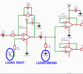
Just a quick question. Do you think that this circuit of the op-amp headphone amp is correct. LTSpice says yes but I would like to know your opinion. VCC = 12V and Bias voltage is 6V.
Thank you.

Just a quick question. Do you think that this circuit of the op-amp headphone amp is correct. LTSpice says yes but I would like to know your opinion. VCC = 12V and Bias voltage is 6V.
Thank you.
It shouldn't work well. The last stage has no offset. And why do you have so many stages?
The transistor on the input also has no bias, it may produce distortion and I saw in the datasheet of the JFE2140 JFET that it has a lower input voltage noise with higher bias.
The transistor on the input also has no bias, it may produce distortion and I saw in the datasheet of the JFE2140 JFET that it has a lower input voltage noise with higher bias.
If you run the simulation with a higher imput level you will see what will happen, it will most likely clip to ground.
Volume control cannot see DC voltage.
Please study this.
https://www.ti.com/lit/an/sloa030a/sloa030a.pdf
Please study this.
https://www.ti.com/lit/an/sloa030a/sloa030a.pdf
I would use 2 5532 chips tied together with 47 ohm resistors. The single gain stage drives a 10k pot to the output op amps. Pot has 10uf on input and .1uf on wiper into 100k resistor.
1. the 2nd and 4th stages are pointless. You can do a bit of gain in the output so the 3rd stage is also pointless.
2. the volume control is wired wrong.
3. R9 and the ground connection are wrong. Remove it.
4. R10 just adds noise. Match R2 or better just direct connection to the bias voltage.
5. R11 is pointless.
6. R15 needs to connect to bias, not ground.
7. you need about 600/30=20 typical op-amps in parallel to drive 30 Ohm headphones, with build-out resistors about 47 Ohms each. You will get some sound with less, but they will quickly current limit. A single discrete buffer or high current chip is recommended.
8. you do not need a Zobel network (R16+C8) for op-amps.
9. you need a coupling capacitor with R20 input to keep the bias voltage off your source and keep it from shorting out the fet bias.
enough!

Well lets see - imagine we want maximum of 100mW into 30 ohms (in practice that's going to instantly deafen you), thats about 1.7V rms 58mA rms.7. you need about 600/30=20 typical op-amps in parallel to drive 30 Ohm headphones, with build-out resistors about 47 Ohms each. You will get some sound with less, but they will quickly current limit. A single discrete buffer or high current chip is recommended.
or about 80mA peak. 3 or 4 5532 stages in parallel could drive that just about, 20 seems like overkill. With 4 they see 120 ohm load each, but at low amplitude that's OK, the 600 ohm lower limit applies to full swing signals, you can handle lower impedances at lower excursions without much problem. Perhaps use 3 5532 packages for 6 stages in parallel?
32 Paralleled NE5532 chips can drive an 8 ohm loadspeaker upto 10W or so, you shouldn't need 10 chips for a mW-level headphone/earphone...
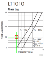
You could investigate using the LT1010 (datasheet here) as a high current buffer, within the feedback loop of an opamp. This creates a composite amplifier with high gain, low distortion, and tons of output current (> 150mA) delivered to the load. If you happen to select a high quality dual opamp such as the OPA2134, you get a stereo headphone amplifier using just three ICs.
I suggest you make a conservative choice for your gain-vs-bandwidth tradeoff. I recommend
_
I suggest you make a conservative choice for your gain-vs-bandwidth tradeoff. I recommend
- (Opamp_GBW_product / Your_HPA_designed_Closed_Loop_gain) < 3.5 MHz . . . . . as shown by the red circle.
_
Attachments
Yes, that's what I had in mind. (https://sound-au.com/project113.htm) I might add a couple diodes for current limit. And the supply voltage could be reduced to something like +/-5V and even smaller transistors. As Mark pointed out, headphones need no more than 1 or 2 VAC. TI's web site has a list of headphone amp chips, but I'd avoid any parts that are not generic.
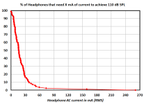
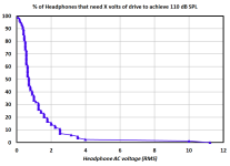
Summarizing the data tabulated in this article on head-fi.org, I've plotted the numbers as cumulative distributions. Beware that 110 dB SPL is ear splittingly loud.
How to read the red curve:
_
How to read the red curve:
- 100% of headphones in the table need 0 mA or more, to produce 110dB SPL
- 20% of headphones in the table need 28 mA or more, to produce 110dB SPL
- 100% of headphones in the table need 0V or more, to produce 110dB SPL
- 35% of headphones in the table need 1V or more, to produce 110dB SPL
_
Attachments
That's why I included the link in my post.
Summarizing the data tabulated in this article on head-fi.org, I've plotted the numbers as cumulative distributions. Beware that 110 dB SPL is ear splittingly loud.
How to read the red curve:
How to read the blue curve:
- 100% of headphones in the table need 0 mA or more, to produce 110dB SPL
- 20% of headphones in the table need 28 mA or more, to produce 110dB SPL
- 100% of headphones in the table need 0V or more, to produce 110dB SPL
- 35% of headphones in the table need 1V or more, to produce 110dB SPL
_
So, 270 mA and 12V to cover them all! Eheh 😆
Or treat the "Hifiman HE-4" and "Hifiman HE-6" as ridiculous outliers; and discard them from your universe of headphones-I-intend-to-drive-at-110-dB-SPL.
Now you need >= 75mA RMS and >= 4.0V RMS
Now you need >= 75mA RMS and >= 4.0V RMS
Or treat the "Hifiman HE-4" and "Hifiman HE-6" as ridiculous outliers; and discard them from your universe of headphones-I-intend-to-drive-at-110-dB-SPL.
Now you need >= 75mA RMS and >= 4.0V RMS
Very wise indeed.
Now, for my much needed education…I know a few people in the audiophile world who say “even if an amp can make them loud, it doesn’t mean it’s driving them properly”.
What do they mean?
Is it about transients and sag? Or is it mostly audiophoolery?
You could investigate using the LT1010 (datasheet here) as a high current buffer, within the feedback loop of an opamp.
Or a BUF634A, which might be cheaper. There is a design which uses the LMH6321 together with an OPA1656:
https://www.diyaudio.com/community/...adphone-amp-using-opa1656-and-lmh6321.362537/
In my opinion the HPA from Elliot doesn't sound that good. I built the amp by myself and it is not so easy to thermally couple the 1N4148 diode to the transistors and the NE5532 meh...
- Home
- Amplifiers
- Headphone Systems
- Headphone amplifier design