Since we were having a discussion on driving low impedance headphone which had poor SPL, I've put some an method of driving these. I have use an audio line level transformer say 6:1 to do the impedance conversion.
.png")
Cheers, I used a similar circuit (without the CCS and 12AU7 not 6N6P) to drive a reverb tank and that worked well.
That's an interesting transformer. Question... Do you know the primary L of that transformer? Was 10H per half-primary a guess, or is that what it is in real life? I didn't see anything about primary L in the data sheet from the Farnell site.
A different way of going about it: SE 6P1P for 32 ohm cans...
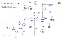
Another way of going about making tubes able to drive 32 ohm cans.... Good ol' NFB. In this case, local plate-grid feedback around a 6P1P (or 6V6, 6AQ5, 12AQ5, etc.). The input tube is 6AK5 = EF95 = 5654 = 6J1P (Russian) = 6J1 (Chinese)
Attached schematic.
One problem I see is finding those high-dissipation, high-value resistors. 100k 2W, 47k 5W. They're hard to find. Mills wirewound would be nice. Expensive, though.
The OPT is Edcor XSE10-8K-50 (12.5:1), which I think still costs under $25 each in the USA.
The simulation says about 0.5% THD at 1V RMS out (31mW) into 32 ohms (or 50 ohms). Gain is 5.8X (kind of high for a headphone amp, but in the ballpark).
Criticisms?
What do you think?
--
Attachments
Last edited:
It is a guess. Basically its still got to work as a transformer at 30Hz so that will determine the primary inductance. The PP has lower distortion. I was avoiding SE as it put current through the transformer and so is not suitable for audio transformers.
Last edited:
If you stick to carbon or metal oxide 47K 5W is not a problem. How come you have C3 up to supply?
Last edited:
Having looked at a range of audio transformers the 150 secondary is more likely to be 500mH and the half the primary 20H. Its very important not to saturate these devices with DC.
It seems there are metal film 5W resistors in higher values these days, which would be better than metal oxide (I don't like to use MOX resistors as plate loads in amps without feedback but I don't know if that makes a difference in a feedback amplifier). Mills and Ohmite make good wirewound 47k 5W resistors.
C3 goes to the B+ because B+ is ground too ("Ultrapath" configuration), so it works to bypass audio frequencies around the cathode resistor and at the same time serves to bypass the zener that regulates the screen supply for U1 (the 6P1P). C3 could also go to ground (0V), with its positive end to the 6P1P cathode and its negative end to ground, but then it wouldn't bypass the zener. On the other hand, the Ultrapath cap couples any ripple that might be on the B+ to U1's cathode, so the B+ supply does need to be quiet.
I imitated that 'Ultrapath' trick from Micheal J Koster's 'Schadeode' SE amplifier, which is basically the same as this except it uses a depletion mode MOSFET instead of U2 (the 6AK5).
Schadeode
That could also be used to make a good headphone amp with a 6V6-oid, but matching the MOSFETs might be a pain.
--
Having looked at a range of audio transformers the 150 secondary is more likely to be 500mH and the half the primary 20H. Its very important not to saturate these devices with DC.
20H would be a lot! I guess since they're not rated to take any quiescent current through the primary, that could be how they get such high inductance.
How do you enforce zero standing current in the OPT primary?
--
Maybe it would be fun to use a 1:1+1 input transformer to split phase, then make a single differential pair out of a pair of RF Pentodes strapped triode (something like D3a or 6J52P) and put a CCS with bypass cap in the cathode of each output tube. That should enforce zero standing current in the OPT primary.
Another possibility could be a 6DJ8 LTP to split phase and supply a little gain, into a push-pull pair of 6N6P, each with a bypassed CCS in its cathode.
--
Another possibility could be a 6DJ8 LTP to split phase and supply a little gain, into a push-pull pair of 6N6P, each with a bypassed CCS in its cathode.
--
Last edited:
I don't think you will find any difference at audio frequencies between modern resistors. You are correct in that I would need to add a 47R pot on the cathodes to the CCS to ensure current balance. Not ideal. Another idea is to use the WCF from the original post and add a transformer. No DC there and the feedback can now go to the first cathode rather than the grid.
.png")
Works better with lower ratio transformer.
Works better with lower ratio transformer.
Last edited:
Maybe it would be fun to use a 1:1+1 input transformer to split phase, then make a single differential pair out of a pair of RF Pentodes strapped triode (something like D3a or 6J52P) and put a CCS with bypass cap in the cathode of each output tube.
--
Here's a version with input transformer split using acorn tubes:
955 acorn tube headphone amplifier - diyparadise
Yep that would work. Does give a high impedance on the cans - I don't know if that a problem or not.
The problem I've had with PP headphone amps based on a twin-triode with low-ish rp (like 6DJ8 or 6N6P) is that the step-down ratio of the OPT means the final amp is right around unity gain. No room for any NFB, which means the quality of the OPT defines the quality of the sound you get, which means $$$.
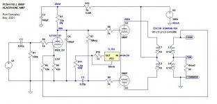
I was looking at adding a gain stage in front of the PP output stage and came up with something that looks promising. Basically, it's a 'Mullard' style driver stage from a typical PP power amp, but with the output tubes taken out. The LTP plates connect to the OPT primaries, so the LTP performs both phase splitting and power output functions. That's the idea behind the 'OddWatt' amplifiers.
The open loop gain should be about 8X, so you can add 6dB of NFB to arrive at 4X gain. That's about normal for a headphone amp.
I don't know if LTspice can be believed, but it's fantasizing about incredibly low THD figures, even open loop. I don't know...
Schematic attached. I can upload the .asc file if you like.
--
Attachments
Last edited:
Similar to post #1 but you will save a tube on a stereo amp. You have DC coupling from first stage to bias LTP. You will still have the DC balance problem but a 5W transformer helps. You may need a resistor in series with C4 for stability. The FB helps keep the output impedance down. You can get more open loop gain by bypassing R4 with RC. You could even use pentode first stage.
Last edited:
- Home
- Amplifiers
- Tubes / Valves
- Headphone amp for 32R cans