To all,
Regarding the circuit as shown below, I like to know whether anyone has seen this front-end before. If so, I'm curious to learn more about it and how it behaves in real life. More details can be found here.
(BTW, I'm still editing and updating that page, so it's not yet finished)
Cheers,
E.
Regarding the circuit as shown below, I like to know whether anyone has seen this front-end before. If so, I'm curious to learn more about it and how it behaves in real life. More details can be found here.
(BTW, I'm still editing and updating that page, so it's not yet finished)
Cheers,
E.
Attachments
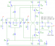
Haven't worked on this before but a very interesting design. Would I be right to say the 2nd stage current is set by the mirrors. If so, how precise must Q2 and Q3 be.
Am I seeing folded cascodes and cascodes in the 2nd stage?
Am I seeing folded cascodes and cascodes in the 2nd stage?
how do I1 & I2 get current from/to the supply rails?
The only route I can see is through the shorted CtoB of Q2 & 3
The only route I can see is through the shorted CtoB of Q2 & 3
Haven't worked on this before but a very interesting design. Would I be right to say the 2nd stage current is set by the mirrors. If so, how precise must Q2 and Q3 be.
Hi Michael,
Yes, that right, but more precisely, Iq of the 2nd stage (the TIS) is defined by the tail current of the LTPs, which is reflected by the current mirrors.
If so, how precise must Q2 and Q3 be.
Well, these transistors should be reasonably matched, just as with any other current mirror.
Am I seeing folded cascodes and cascodes in the 2nd stage?
That's also correct, that is, the 'right legs' of the LTPs are 'folded', whereas the 'left legs' are connected via the current mirrors to the TIS.
Cheers,
E.
When I've finished the description on my website and you have read it, I hope you will understand the specific virtues of this circuit .I fail to see what this brings over more conventional approaches . . .
Cheers,
E.
Wow.
You guys are brilliant. Seriously, I just take a look and try to figure out how this works in a rudimentary way (out of interests sake and I have read those recommended books) and then you guys can disect and discuss it in no time flat.
Just something I noticed.
You guys are brilliant. Seriously, I just take a look and try to figure out how this works in a rudimentary way (out of interests sake and I have read those recommended books) and then you guys can disect and discuss it in no time flat.
Just something I noticed.
Thanks for your confirmation, Edmond.
Looking at the circuit again, I should re-phrase my question. It's not the matching of Q2 and Q3 but rather the current sources I1 and I2 that I'm concerned with. They need to be exact in order to derive the full benefits of this symmetry concept.
With opamp manufacturing, it is not an issue. However, using discretes, I have encountered difficulties in getting both current sources to be equal. Is there an easy solution.
By the way, thanks for sharing your design. I think there would be a real reduction in THD20. Very elegant.
how do I1 & I2 get current from/to the supply rails?
The only route I can see is through the shorted CtoB of Q2 & 3
Hi Andrew,
Good point. Indeed through the shorted CtoB of Q2 & 3.
How exactly I will show in one of the following updates of my website.
Cheers,
E.
Thanks for your confirmation, Edmond.
Looking at the circuit again, I should re-phrase my question. It's not the matching of Q2 and Q3 but rather the current sources I1 and I2 that I'm concerned with. They need to be exact in order to derive the full benefits of this symmetry concept.
Hi Michael,
Now understand your question better. I1 and I2 don't need to be exactly equal, though a difference does have a profound on the voltage- and current-offset.
With opamp manufacturing, it is not an issue. However, using discretes, I have encountered difficulties in getting both current sources to be equal. Is there an easy solution.
Don't worry. The circuit still works if I1=2*I2 ! If you keep it within a few percent, everything is fine.
By the way, thanks for sharing your design. I think there would be a real reduction in THD20. Very elegant.
Thank you!
But my question was: Is it new; has anybody seen it before?
Cheers,
E.
Last edited:
Hello,
I have seen similar front ends.
Q1 to Q6, Q9 and Q12 are similar to the complimentary differential input stage with current mirror loads shown in Figure 7.9 of 'Designing Audio Power Amplifiers by Bob Cordell. Q7, Q8, Q10 and Q11 are different. The double differential input configuration is also shown in the 'Audio Power Amplifier Design Handbook' , Fifth edition, figure 5.12 by Douglas Self.
I believe that rail to rail input operational amplifiers use the NPN and PNP differential pairs for the commom mode range.
it looks like one of the circuits developed by Hawksford.
see his distortion correction for audio amplifier circuits paper.
see his distortion correction for audio amplifier circuits paper.
Hello,
I have seen similar front ends.
Q1 to Q6, Q9 and Q12 are similar to the complimentary differential input stage with current mirror loads shown in Figure 7.9 of 'Designing Audio Power Amplifiers by Bob Cordell. Q7, Q8, Q10 and Q11 are different.
Hi PChi,
That's the precisely the point: "Q7, Q8, Q10 and Q11 are different."
The double differential input configuration is also shown in the 'Audio Power Amplifier Design Handbook' , Fifth edition, figure 5.12 by Douglas Self.
I believe that rail to rail input operational amplifiers use the NPN and PNP differential pairs for the common mode range.
I've checked those books (of course) but nothing comes close. It's not about the double (i.e. complementary) input stage, rather the Baxandall super pair in the TIS (or VAS if you like, a misnomer btw)
Cheers,
E.
it looks like one of the circuits developed by Hawksford.
see his distortion correction for audio amplifier circuits paper.
Hi myhrrhleine,
You are on the right track. Indeed, the Baxandall super pair closely resembles the Hawksford cascode (hence the reference to his article on my website), but a crucial difference is that my TIS has a current gain of just 1x (instead of beta or even beta^2).
Cheers,
E.
E.
It has lots of similarity to a number of circuits. Cherry at first came to mind, but the exact design with your intent seems like a new twist. (The adage of enough chimps pecking at typewriters will eventually produce Shakespeare comes to mind, preventing an absolute claim at exclusivity.)
So go for it!
ES
I have never seen or done something exactly identical.
I have used variants, mainly without the cascodes, and with the collectors of Q5/Q6 directly tied to R15/R16.
A sort of an afterthought, a way to recycle an active current that would otherwise be wasted.
But anyway, I am not very fond of double LTP's and their closed translinear loop, I didn't mind very much, and I didn't notice anything extraordinary.
I may have missed something.....
- Status
- Not open for further replies.
- Home
- Amplifiers
- Solid State
- Has anyone seen this front-end before?