I wonder if someone has tried a LPS with its own linear regulator to be used to power the Opamps at the input of a tpa3255 board ?
Continuing my tpa3255 amplifier building, the sound is very good as it is, but I guess it can be even better ?
The op amps I use is two opa1612 . The power supply for both opamps on the board, uses a xl7015 regulator with DC from a 36V 6A smps power brick. The DC power for the opamps is 12V.
Looking at the pin configuration, it seems like pin four and eight is for -V and +V .
Can this mod be done by simply cutting the two pin-legs on the IC adaptor ( dissabling -V and +V ) , then soldering two cables to the -V and +V points marker in red on the picture ,and use a linear supply with lm317 I have ?
Is it a safe mod to do this ( I hope no common signal ground at pin 4 ? ) .
Is there audible differences for the better to try driving the opamps with linear regulators ? Whats your experience ?
Last edited:
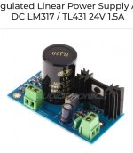
Picture of my LPS powersupply with lm317, variable voltage output.( I have the 15V transformer out of picture )
But I wonder if one can use a single power supply directly on opa1612 pin 4 and 8 or must I create a virtual ground for this ?
But I wonder if one can use a single power supply directly on opa1612 pin 4 and 8 or must I create a virtual ground for this ?
Attachments
Last edited:
I have seen linear toroidal PSU used for main amp power even. The TPA3255 amp implementations typically have a buck converter that is then regulated using a linear regulator on board.
Here is LPS implementation by Vunce

You can bypass the buck and feed it 15v directly from external linear source which then is dropped to 12v on board. I have done this before on my amp when the DCDC buck converters once were out of stock due to supply issues after Covid.
Here is bypassing on board DCDC Buckconverter with external 15v LM7815 regulated auxiliary power supply.

Here is LPS implementation by Vunce
You can bypass the buck and feed it 15v directly from external linear source which then is dropped to 12v on board. I have done this before on my amp when the DCDC buck converters once were out of stock due to supply issues after Covid.
Here is bypassing on board DCDC Buckconverter with external 15v LM7815 regulated auxiliary power supply.
Last edited:

Thanks srk791.
Is it safe to just cut the två pins in the DIL8 capsule for -V and +V ( to disable the power coming from the tpa3255 board ) and solder a new cable on pin 4 and 8 to an external LPS , 12-15 V DC ?
No virtual ground to have to deal with ?

Is it safe to just cut the två pins in the DIL8 capsule for -V and +V ( to disable the power coming from the tpa3255 board ) and solder a new cable on pin 4 and 8 to an external LPS , 12-15 V DC ?
No virtual ground to have to deal with ?
I think you can do that but you need to reference the external PSU GND to the TPA3255 main power GND.
You can also use a completely external balanced driver preamp and drive the inputs directly through a coupling cap.
OPA1637 is good for this.
You can also use a completely external balanced driver preamp and drive the inputs directly through a coupling cap.
OPA1637 is good for this.
More recent TPA3255 boards now utilize a linear regulator:
https://www.ebay.com/itm/156131230527
Description states:
"The auxiliary power supply uses Class A linear power supply, which is more dynamic, and the sound quality is significantly improved!"
Rather than hack your current board I would just buy one of these new boards and try first as they are so inexpensive.
I see this board on aliexpress as well.
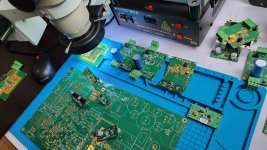
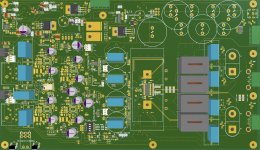
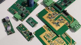
To address this issue, I developed the second revision of the TPA3255 PCB, incorporating PFFB. The design includes a TPS7A470x powering an LT3045 for the positive rail (POS) and a TPS7A3301 powering an LT3094 for the negative rail (NEG), both embedded in the PCB and positioned close to the VCC and VEE supply pins of all operational amplifiers. The combination of low-noise, high-PSRR voltage regulators, polymer OSCON capacitors, and an optimized PCB layout plays a crucial role in minimizing switching noise. I made many versions of the LT3045 and LT3094 for my hobby.
P.S. the best is dual supply.
P.S. the best is dual supply.
Attachments
I fully agree, coming from another background in amplifier technology, I have wondered why so few does this. The asymmetrical SE to BAL with two opamps, that seems to be industry std should in my opinion be substituted.You can also use a completely external balanced driver preamp and drive the inputs directly through a coupling cap.
A real symmetrical driver wether being an OPA1637, input transformer(no secondary CT!), discrete sand or tube circuitry should do a better job, when using TPA32xx in highend applications.
Personally I would prefer a good transformer like Lundahl, as you get galvanic isolation and at the same time gets rid of the input capacitors. Have not tried it yet, but will eventually do, using LL1544A that I have in stock.
In case of using active external circuitry, you have your own choice of power supply and film input capacitors
Last edited:
I currently have an OPA1637 balanced driver going to the inputs of the TPA3255 followed by NE5532 in TI ref design. I could try jumpering the on board opamps to go direct drive.
Reason not to use transformers might be they are expensive vs $0.35 capacitor (Elna Silmic II 10uF). Also, they have some intrinsic distortion signature (odd orders typical of transformers).
Reason not to use transformers might be they are expensive vs $0.35 capacitor (Elna Silmic II 10uF). Also, they have some intrinsic distortion signature (odd orders typical of transformers).
Moddang - Thanks for info regarding the LT3045 and LT3094. I downloaded data sheets. Very good PSRR on these devices.
Dual ended supply is nice but I'm not sure it is worth all the extra cost and effort.
But your project is very commendable by going to all ends to get the best possible result out of the TPA3255.
Do you have some data comparing your board with one of the low cost variants?
Substituting a good quality polypropylene coupling capacitor on a low cost board with single ended supply may be worthwhile.
But I agree reducing PS noise on input opamps for low cost boards is crucial.
I would really appreciate it you jumped the onboard critters. So anxious to know if you hear any differencies in your system.
About trannys they are really expensive, one of them normally cost more than a fully populated TPA3255 stereo board.
I am suspicious to use an electrolytic in an environment where no potentional differencies exists at each side.
About distortion figures there will be no odd order problems, as long as you keep out of saturation levels. As 3rd harmonic seems to be dominating over 2nd order in a 3255, I agree no more need to be added.
Anyway a blind test would be nice to do, but it will never happen ;-) .
Cheers
Lars
Reason not to use transformers might be they are expensive vs $0.35 capacitor (Elna Silmic II 10uF). Also, they have some intrinsic distortion signature (odd orders typical of transformers).
About trannys they are really expensive, one of them normally cost more than a fully populated TPA3255 stereo board.
I am suspicious to use an electrolytic in an environment where no potentional differencies exists at each side.
About distortion figures there will be no odd order problems, as long as you keep out of saturation levels. As 3rd harmonic seems to be dominating over 2nd order in a 3255, I agree no more need to be added.
Anyway a blind test would be nice to do, but it will never happen ;-) .
Cheers
Lars
Moddang - Thanks for info regarding the LT3045 and LT3094. I downloaded data sheets. Very good PSRR on these devices.
Dual ended supply is nice but I'm not sure it is worth all the extra cost and effort.
But your project is very commendable by going to all ends to get the best possible result out of the TPA3255.
Do you have some data comparing your board with one of the low cost variants?
Substituting a good quality polypropylene coupling capacitor on a low cost board with single ended supply may be worthwhile.
But I agree reducing PS noise on input opamps for low cost boards is crucial.
- Sorry, I have not made any comparisons with the low-cost board.
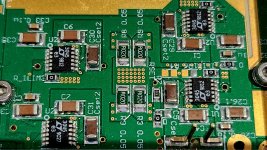
- Substituting a good quality polypropylene (MKP) coupling capacitor on a low-cost board may not be possible as it is very bulky and also costly. How many decoupling and coupling capacitors do you need for a single-supply op-amp? You will need at least 10µF, but the best option should be more than 20µF to extend to lower frequencies.
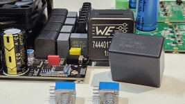
For this project, I do not care about cost. For example, I use high-quality components such as an LC filter with the 7444013119100 MnZn inductor, which has a high/hard saturation current and is better than conventional iron alloy inductors. For capacitors, I use High Pulse DV/DT MKP capacitors. For the chip resister at least it should be thin film size 1206 for the audio signal path to minimize the distortion. I would say all of these is not fancy. The board that I designed has option to put the OPA1632 external fully balanced driver direct to the inputs DC block in front of the TPA3255. This PCB is 4-layers 2Oz. For me, the main key for this project is not the components but the first thing is the PCB layout.
Attachments
Probably 4 strategic cuts to the PCB and 4 jumper wires should do the trick. Studying the layout traces to make sure I cut the right lines will require some time to study. It’s been a while since this board was designed so my memory has faded.I would really appreciate it you jumped the onboard critters. So anxious to know if you hear any differencies in your system.
About trannys they are really expensive, one of them normally cost more than a fully populated TPA3255 stereo board.
I am suspicious to use an electrolytic in an environment where no potentional differencies exists at each side.
About distortion figures there will be no odd order problems, as long as you keep out of saturation levels. As 3rd harmonic seems to be dominating over 2nd order in a 3255, I agree no more need to be added.
Anyway a blind test would be nice to do, but it will never happen ;-) .
Cheers
Lars
- Home
- Amplifiers
- Class D
- Has anybody tried a LPS just for the opamps used with TPA3255?