Hello.
This is obvious enough it shouldn't be only me who's though of it.
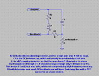
Basically, you sidestep the problem of a capacitor on the output of a class-A amp by taking the feedback signal from point after the main output capacitor.
Here's a quick MS Paint scribble that I coughed up to illustrate my point. It should be readable.
If one is clever in their design, one may not need to include a DC blocking capacitor in the feedback path.
- keantoken
This is obvious enough it shouldn't be only me who's though of it.
Basically, you sidestep the problem of a capacitor on the output of a class-A amp by taking the feedback signal from point after the main output capacitor.
Here's a quick MS Paint scribble that I coughed up to illustrate my point. It should be readable.
If one is clever in their design, one may not need to include a DC blocking capacitor in the feedback path.
- keantoken
Attachments

Yes.
This has been done many times in the past.
Both in pre- and power amplifiers.
If coupling this feedback rail with capacitor, you get only AC feedback.
This has been done many times in the past.
Both in pre- and power amplifiers.
If coupling this feedback rail with capacitor, you get only AC feedback.
Nelson did it in the ZEN Revisted 1994 article....It's a interesting topology to lineaize the Cap ...
http://www.passdiy.com/pdf/retofzen.pdf
chrz,
T
http://www.passdiy.com/pdf/retofzen.pdf
chrz,
T
or another way would be to make a bridged class A with the speaker connected directly to the outputs (no capacitors). there would be no DC offset across the speaker, but the voice coil would be at a DC potential.... panasonic uses a similar scheme with their class D amps which use a single ended power supply.... another added benefit is double the power. another way to do it WITH the cap would be to do a DC level shift to the feedback. either method would keep reactive components out of the feedback loop.
duhh..... if i had looked at the URL closer i would have known that....
one could also make a class A amp with split rails and a diff amp, and eliminate the output cap that way. it would provide a lower output impedance too... i think the bridged class A is the best way to do it with a single ended supply. it's pretty easy to make an inverting buffer suitable for the application. as a matter of fact the Dynaco amp could be operated like that without output caps, you just need an ST-120 for each channel....
one could also make a class A amp with split rails and a diff amp, and eliminate the output cap that way. it would provide a lower output impedance too... i think the bridged class A is the best way to do it with a single ended supply. it's pretty easy to make an inverting buffer suitable for the application. as a matter of fact the Dynaco amp could be operated like that without output caps, you just need an ST-120 for each channel....
Another excellent example (and not only in this regard):
http://www.angelfire.com/ab3/mjramp/simple1.html
- Klaus
http://www.angelfire.com/ab3/mjramp/simple1.html
- Klaus
This is great, now I have some more study material.
Are there any downsides to doing this?
- keantoken
Are there any downsides to doing this?
- keantoken
Any downsides?
No, not more than anything else.
There are benefits / drawbacks with most any choice in amplifiers details.
It is more about:
When you do something you should do this in correct (= best) way.
No, not more than anything else.
There are benefits / drawbacks with most any choice in amplifiers details.
It is more about:
When you do something you should do this in correct (= best) way.
why is capacitive coupling on the output seen as such a bad thing? i will be the first to admit my ears are not the greatest, (they are the victims of much abuse, lol) but i honestly cannot tell the difference. i have taken direct coupled amps and just for kicks installed ~470uF series between out+ and speaker+ and can't for the life of me hear (or see on the scope or dist analyzer) any differences.
flame shields up 🙂
flame shields up 🙂
gain said:why is capacitive coupling on the output seen as such a bad thing? i will be the first to admit my ears are not the greatest, (they are the victims of much abuse, lol) but i honestly cannot tell the difference.
i have taken direct coupled amps and just for kicks installed ~470uF series
between out+ and speaker+
and can't for the life of me hear (or see on the scope or dist analyzer) any differences.
flame shields up 🙂
You are in good company, gain.
I am of same opinion as oldtimers like Hugh AKSA Dean and Nelson Pass:
A modern output electrolytic capacitor in power amplifiers
wont hurt your sound a bit
.. and we know how difficult it is to measure capacitor distortion
.. because if using the best, there is hardly anything to measure
.. and of course even less to hear with your ears
There are others, that say & think the opposite.
For example, I cant imagine Mr John Curl accepting an output capacitor
.... probably over his DEAD BODY 😀
Hmm. I've heard someone say though that they were able to observe changes in capacitance when they squeezed an electrolytic. I imagine that in a speaker enclosure, the pressure might cause some problems.
In any case, since capacitor distortion has been observed (at least on an oscilloscope), it makes sense to me that someone would try this. It also makes sense to me because it should also extend the frequency response. And you know how some people like bass. 🙂
If this is used with too little a coupling capacitor though, it might be possible to blow the amp. So if I designed something like this I would do something like this.
- keantoken
Attachments
- Status
- Not open for further replies.
- Home
- Amplifiers
- Solid State
- Has any one done this before?