here is a hardman with some weird behaviour
the unit is in mint condition everything is fine all cps are replaced inside but offset doesnt want to cope in any possible way
multiturns are installed ofset can be easilly set to zero but in any temperature variation offset rides to a100 or 200 or 300 millivolt or more
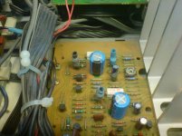
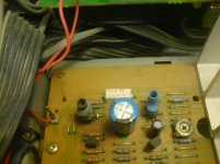
hardman did some excersize on thermal junction actually bolting tranistors in some plastic to ensure full contact and thus balance of temperature between the two semis ....
though it seems that long term stability was effected since a lot of temperature rised inside the bolt resulting to thermal stress of soldering
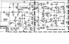
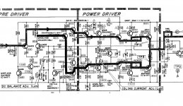
there is a picture of the schematic and pictures of the thermal junction
Q422-426 getting quiet hot and touching the a bit is enough to alter ofset dramatically
any ideas ???
the unit is in mint condition everything is fine all cps are replaced inside but offset doesnt want to cope in any possible way
multiturns are installed ofset can be easilly set to zero but in any temperature variation offset rides to a100 or 200 or 300 millivolt or more
hardman did some excersize on thermal junction actually bolting tranistors in some plastic to ensure full contact and thus balance of temperature between the two semis ....
though it seems that long term stability was effected since a lot of temperature rised inside the bolt resulting to thermal stress of soldering
there is a picture of the schematic and pictures of the thermal junction
Q422-426 getting quiet hot and touching the a bit is enough to alter ofset dramatically
any ideas ???
Attachments
checked all voltages it is with in 10% according to the schematics everywhere
that is strange eee
that is strange eee
temperature over transistors 426-422 is almost 65 degrees ...that is way too much i think
Have you checked the value of all the fusible (safety) resistors in this amp? Maybe one (or more) of them has drifted in value.
Steve.
yes i did ...also i have checked all voltages according to the schematic and all seems fine ... also replaced a few resistors that looked susspicious but made no diference
Harman Kardons are prone to offset drifting because they use low over all global feedback.
You can set the offset at the correct level and then a few minutes later it may have drifted a few tens of millivolts. This is perfectly normal with this type of design. Also they are biased to run fairly warm.
regards
Trevor
You can set the offset at the correct level and then a few minutes later it may have drifted a few tens of millivolts. This is perfectly normal with this type of design. Also they are biased to run fairly warm.
regards
Trevor
thanks for your input ...yes it could be ok with a few millivolts variations though like 300 millivolt plus or minus is too much
yet again 65 degrees over the 426-422 tranistors is also too much ... there is got to be something else wrong
as about the bias ...service manual says 30 millivolt over the emmiter resistors ...that is equal to nothing i presume ....also main heatsink stays relativelly cold only these tranistors are boilig
thanks
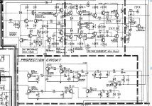
if any body cares to help or see there is a strange protection circuit that i ve never seen before ... and i thought that it might be a good idea to remove it to see if this is effecting the offset stabilty ... as you can see there is two troubles ...one is the ofset stability and the other is the overheating of the transitors
here is the protection
here is the protection
Attachments
i could see perhaps a faulty q418 or a fault in the protection circuit messing with it. might be worth pulling that temporarily?
what was the original fault?
what was the original fault?
what the costumer could see was the cones of the woofers going in and out due to extreme ofset variations that was with no music playing and randomly appeared
looking at the way hardman made the thermal junctions and a lot of soldering issues that was repaired i thought that this was the cause ...but it wasnt
then again i wonder if these two mosfets 401 402 are responsible to mute the amp or to inject voltage in the input to stabilize ofset ...that all is weird to me at least
thanks jay cee
Hi sakis,
Harmon Kardon is famous for running transistors close to their maximum ratings, and runs them hot just for good measure. With these, expect to see the most off-beat semiconductor problems. Measuring C-E and C-B leakage is very important in these situations. You may even see beta shifting wildly with temperature, but my bet is on junction leakage.
The short answer - shotgun the signal stage, up to and including the driver transistors. Anyone who is familiar with the way I look at service will immediately notice that I have just recommended something about opposite to my normal advice. There is a good reason for this. Take care matching your new matched pairs. This circuit really needs this. Also, lose the multi-turn pot. It will not be your friend in a few years, you really want the extra contact area that exists in the single turn controls.
Notice that your DC offset control will only apply negative current into the diff pair. Have you been able to measure both input pair base voltages? This can tell you something sometimes. The customer's report of woofers going back and forth tells me that the protection circuit isn't very effective unless you have a large, coil burning DC offset. Nice of them. Also notice that the drivers are connected in a CFP configuration, and that RF chokes have already been installed (to tame oscillation no doubt). So make sure something isn't oscillating both before and after you replace the transistors.
Also, take note of the connections of Q422 and Q426. They are in parallel! I guess they couldn't find a single transistor that would put up with the circuit position. Since these are running hot, and Q424 and Q428 are not (since you didn't mention they were), Check Q436 and Q440 very carefully for leakage. If these were very leaky, the amount of leakage would be very dependent on temperature and would cause Q422 and Q426 to run hotter. The differential pair may not have enough range to correct for massive changes in leakage in Q436 or Q440.
One last point. Since the other channel is not exhibiting these faults, the basic design seems to operate okay. There shouldn't be any reason to use parts or methods that differ from the working channel (like trimmer controls). One very good reason to change part types is the high temperatures the design subjects the existing parts to. Just watch the stability after making substitutions.
Can you please let me know what the supply voltages are? I'm guessing about +/- 44 VDC for now. Q422, Q422, Q422 and Q426 are rated for 120 VDC, 900 mW and 100 mA each. I'd suggest a TO-126 (or similar) device with a small heat sink be used in these locations as jaycee correctly pointed out. You can figure out the current by measuring across the 150 ohm resistors and select something with a breakdown of 120 VDC or better. You could even double them up if you can figure out a mechanical solution for the heat sink. Watch the capacitance here.
Let us know how this works out for you!
-Chris
Harmon Kardon is famous for running transistors close to their maximum ratings, and runs them hot just for good measure. With these, expect to see the most off-beat semiconductor problems. Measuring C-E and C-B leakage is very important in these situations. You may even see beta shifting wildly with temperature, but my bet is on junction leakage.
The short answer - shotgun the signal stage, up to and including the driver transistors. Anyone who is familiar with the way I look at service will immediately notice that I have just recommended something about opposite to my normal advice. There is a good reason for this. Take care matching your new matched pairs. This circuit really needs this. Also, lose the multi-turn pot. It will not be your friend in a few years, you really want the extra contact area that exists in the single turn controls.
Notice that your DC offset control will only apply negative current into the diff pair. Have you been able to measure both input pair base voltages? This can tell you something sometimes. The customer's report of woofers going back and forth tells me that the protection circuit isn't very effective unless you have a large, coil burning DC offset. Nice of them. Also notice that the drivers are connected in a CFP configuration, and that RF chokes have already been installed (to tame oscillation no doubt). So make sure something isn't oscillating both before and after you replace the transistors.
Also, take note of the connections of Q422 and Q426. They are in parallel! I guess they couldn't find a single transistor that would put up with the circuit position. Since these are running hot, and Q424 and Q428 are not (since you didn't mention they were), Check Q436 and Q440 very carefully for leakage. If these were very leaky, the amount of leakage would be very dependent on temperature and would cause Q422 and Q426 to run hotter. The differential pair may not have enough range to correct for massive changes in leakage in Q436 or Q440.
No, those J-Fets are only there to short the input signals to ground. It is also possible to have leakage there, but those 100 uF 10 VDC capacitors should block DC. I always replace any capacitors rated less than 16 VDC. From experience, only 16 VDC capacitors and up seem to be reliable - all other things considered equal.then again i wonder if these two mosfets 401 402 are responsible to mute the amp or to inject voltage in the input to stabilize ofset
One last point. Since the other channel is not exhibiting these faults, the basic design seems to operate okay. There shouldn't be any reason to use parts or methods that differ from the working channel (like trimmer controls). One very good reason to change part types is the high temperatures the design subjects the existing parts to. Just watch the stability after making substitutions.
Can you please let me know what the supply voltages are? I'm guessing about +/- 44 VDC for now. Q422, Q422, Q422 and Q426 are rated for 120 VDC, 900 mW and 100 mA each. I'd suggest a TO-126 (or similar) device with a small heat sink be used in these locations as jaycee correctly pointed out. You can figure out the current by measuring across the 150 ohm resistors and select something with a breakdown of 120 VDC or better. You could even double them up if you can figure out a mechanical solution for the heat sink. Watch the capacitance here.
Let us know how this works out for you!
-Chris
thanks for coming in Chris ...well both chanels are having the exact same problems .... since its almost midnight i will read your post again tomorow and run diagnostics based on it for every spot ...
I ll get back to you with my results
Thanks for the input best regards and always be well my friend !!
I ll get back to you with my results
Thanks for the input best regards and always be well my friend !!
Hi sakis,
Harmon Kardon is famous for running transistors close to their maximum ratings, and runs them hot just for good measure. With these, expect to see the most off-beat semiconductor problems. Measuring C-E and C-B leakage is very important in these situations. You may even see beta shifting wildly with temperature, but my bet is on junction leakage.
The short answer - shotgun the signal stage, up to and including the driver transistors. Anyone who is familiar with the way I look at service will immediately notice that I have just recommended something about opposite to my normal advice. There is a good reason for this. Take care matching your new matched pairs.there is no point for that ...it seems that none of the semis is damaged but i will reverify that once more more carefully This circuit really needs this. Also, lose the multi-turn pot. It will not be your friend in a few years, you really want the extra contact area that exists in the single turn controls. ( will do that no probs at least i will use sealled and bourns )
Notice that your DC offset control will only apply negative current into the diff pair. Have you been able to measure both input pair base voltages? yes everything is according to the schematic ...or at least the same at the base of ltp pair This can tell you something sometimes. The customer's report of woofers going back and forth tells me that the protection circuit isn't very effective unless you have a large, coil burning DC offset.there is no relay protection ...only what you ve seen in the above schematic Nice of them. Also notice that the drivers are connected in a CFP configuration, and that RF chokes have already been installed (to tame oscillation no doubt). So make sure something isn't oscillating both before and after you replace the transistors. ( by the concept that nothing is broken i dont have much to replace but as i said i will double check )
Also, take note of the connections of Q422 and Q426. They are in parallel! I guess they couldn't find a single transistor that would put up with the circuit position. Since these are running hot, and Q424 and Q428 are not (since you didn't mention they were),they do also get hot but not that much ...say the one pair reaces almost 65 degress and the other one is arround 50 still this a lot for this type of semi Check Q436 and Q440 very carefully for leakage. If these were very leaky, the amount of leakage would be very dependent on temperature and would cause Q422 and Q426 to run hotter. will double check again The differential pair may not have enough range to correct for massive changes in leakage in Q436 or Q440.
Quote:
then again i wonder if these two mosfets 401 402 are responsible to mute the amp or to inject voltage in the input to stabilize ofset
No, those J-Fets are only there to short the input signals to ground. It is also possible to have leakage there, but those 100 uF 10 VDC capacitors should block DC. I always replace any capacitors rated less than 16 VDC. From experience, only 16 VDC capacitors and up seem to be reliable - all other things considered equal. all capacitors of the unit are allready replaced
One last point. Since the other channel is not exhibiting these faults, the basic design seems to operate okay.no...the other chanel has the exact same problems ....so that is a bit of dead end ...at least for crossreference There shouldn't be any reason to use parts or methods that differ from the working channel (like trimmer controls). One very good reason to change part types is the high temperatures the design subjects the existing parts to. Just watch the stability after making substitutions.
Can you please let me know what the supply voltages are? end of the post i will post a part of the schematic that has voltages on it ...and all of them a pretty much ok i think I'm guessing about +/- 44 VDC for now. Q422, Q422, Q422 and Q426 are rated for 120 VDC, 900 mW and 100 mA each. I'd suggest a TO-126 (or similar) device with a small heat sink be used in these locations as jaycee correctly pointed out. You can figure out the current by measuring across the 150 ohm resistors and select something with a breakdown of 120 VDC or better. You could even double them up if you can figure out a mechanical solution for the heat sink. Watch the capacitance here.
Let us know how this works out for you!
thanks again chris ... i will get back to you
Attachments
if any body cares to help or see there is a strange protection circuit that i ve never seen before ... and i thought that it might be a good idea to remove it to see if this is effecting the offset stabilty ... as you can see there is two troubles ...one is the ofset stability and the other is the overheating of the transitors
here is the protection
The protection circuit is a fast muting circuit designed to kill the signal when there is DC on the output or in an over current situation. It is either on or off so I doubt whether it would have an effect on the offset variation.
Are both channels exhibiting the same problems ?
Hi sakis,
If both channels are showing the same fault, I become more convinced that wholesale replacement of the transistors is the proper course of action here. I rarely recommend this type of action, but those H-K units are very hard on transistors.
Now I see that this amplifier is subjecting these parts to close to their maximum ratings. 111 VDC across parts rated for 120 VDC is cutting things too fine. I'd recommend you increase the voltage ratings for replacement parts to 140 V at the minimum. Parts rated for 160 V or 180 V would be a better idea.
When you measure the DC voltages on the bases of the differential pairs, it will be in the mV. Can you take these measurements for us? 0 VDC is far too coarse to be meaningful in this location when we are expecting figures in the mVs.
Remember, you should be looking at values of leakage. These transistors will otherwise check okay. Also, measure leakage and heat the transistor close to it's normal operating temperature. They may only act up when they are warmer than room temperature.
Thank you for posting a more complete schematic diagram. This is helpful to see the normal circuit voltages.
Best,Chris
oki doki ....got the message ...i ll take it from here and see what can i do
thanks everybody for the input ...i will keep you posted
thanks everybody for the input ...i will keep you posted
Harman Kardons are prone to offset drifting because they use low over all global feedback.
You can set the offset at the correct level and then a few minutes later it may have drifted a few tens of millivolts. This is perfectly normal with this type of design. Also they are biased to run fairly warm.
regards
Trevor
Interesting problem, and it also appears at a quick glance that the global feedback return is DC coupled... it just all has that look of running on a knife edge to me.
If it's so critical, then even running with the top off or during the warm up phase I imagine would cause significant drift...
havent seen anything that is weird regarding oscilation ... only anatech's sugestion makes sense so far IE that all transitors in the specific are leacky under load and increase temeprature and offset and the all thing gets messed up
i will make a test and try to replace the parallel sets with MJE340-350 and use 220R emmiter resitors to see if this is getting me anywhere ...
will see
i will make a test and try to replace the parallel sets with MJE340-350 and use 220R emmiter resitors to see if this is getting me anywhere ...
will see
- Status
- Not open for further replies.
- Home
- Amplifiers
- Solid State
- hardman Kardon..... experts