Hi there,
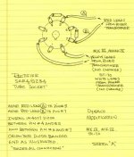
I need some input on a problem with my current amplifier project. It is the well-known PP1C circuit with a few modifications and a power supply using a GZ34 in choke input mode, LCLC. Filtering is 5H, 220µF, 5H, 220µF.
1. One channel is operating fine, it has been switched on and off about 10-20 times in the last months without any problems.
2. The second channel wa finished this weekend. On the bulb limiter, I noticed a short event with the light bulb brightening for the fraction of a second. Nothing else happened and the channel comes up fine, although with reduced rail voltage due to the bulb limiter. Sound is clear without any audible distortion, no smoke or other signs of failure.
3. After operating it for a while, I took out the bulb limiter. As soon as the rectifier starts conducting (rail voltage approx. 40-50V) a bright blue flash appears in the lower part of the rectifier tube, taking out the fuses in both primary legs and even making the room lights flicker for a moment.
OUCH!
Now, I am a bit unsure on how to continue:
a. As the first channel has been working fine all the time, I would not expect the circuit design to be flawed.
b. The recently completed channel works on the bulb limiter, so I would exclude any serious wiring errors.
--> plan A: assume the second GZ34 JJ is faulty, buy another GZ34 and try again
--> plan B: do the above, but wait for forum responses before trying again
I appreciate any input!
kind regards,
Andreas
Last edited:
As the first channel has been working fine all the time, I would not expect the circuit design to be flawed.
Are these monoblocks? If so, try the "good" GZ34 on the second channel.
Always use the series SS diode tweak, when JJ GZ34/5AR4s are employed. When new rectifiers are purchased, buy Sovtek. All of JJ's Octal production has proved to be highly inconsistent. 😡 The New Sensor offering needs the SS help too, but has much better reliability record.
I prefer UF4007s over 1N4007s with the idea that less switching noise, from the outset, is better. However, the vacuum rectifier blocks any SS diode switching noise from entering the B+ rail. If 1N4007s are already on hand, use them.
I prefer UF4007s over 1N4007s with the idea that less switching noise, from the outset, is better. However, the vacuum rectifier blocks any SS diode switching noise from entering the B+ rail. If 1N4007s are already on hand, use them.
Attachments
Are these monoblocks? If so, try the "good" GZ34 on the second channel.
Not really monoblocks, but the two channels are separated enough to be operated independently while testing. I will try putting the known good rectifier in the second channel tomorrow and report back.
Regards,
Andreas
Always use the series SS diode tweak, when JJ GZ34/5AR4s are employed. When new rectifiers are purchased, buy Sovtek.
I ordered a Sovtek replacement right away. Thought I would get away with the JJ's as the first one worked fine - should have known better...
I want to stay away from the diode tweak, as the whole amp was designed without SS devices on purpose. Not for the idea of 'better' sound, but simply for the design idea. So I don't want to throw the whole idea away because of a bad tube - we'll see...
Regards,
Andreas
Sovtek 5AR4s can get into trouble at the top of the specified voltage range. The SS diode tweak provides the necessary PIV headroom.
There are 2 newish "reissues", Genelex and TungSol, that are supposed to be 100% compliant in their behavior and that the SS diode tweak is not needed. However, they cost $15 to $20 more per tube than the Sovtek. IMO, worthy of mention is the fact that all 3 varieties are manufactured by New Sensor at Saratov, Russia.
There are 2 newish "reissues", Genelex and TungSol, that are supposed to be 100% compliant in their behavior and that the SS diode tweak is not needed. However, they cost $15 to $20 more per tube than the Sovtek. IMO, worthy of mention is the fact that all 3 varieties are manufactured by New Sensor at Saratov, Russia.
Junk the flashed GZ34. Any tube that has had a "flash-over" should be junked imho.
Before replacement, do the "yellow sheed mod", it will save from future broken GZ34.
As for replacement, buy whatever comes handy, there is no generic problem with JJ GZ34.
Also, the choke 5H is smaller then recommended (10H) :
https://frank.pocnet.net/sheets/010/g/GZ34.pdf
The smaller choke might create to large startup load, maybe reducing the first cap
to 60uF might be a simple solution.
The absolute maximum value smoothing capacitor is 60uF. Exceed that and it may kill the GZ34.
1N4007 diodes don't help as the GZ34 still has to drop 60 - 75volts per anode.
1N4007 diodes don't help as the GZ34 still has to drop 60 - 75volts per anode.
The capacitors are simply too big.
Changing the chokes to 10H will only make a small difference, because the current-peaks during the first 1s will still be more than the allowable 750mA.
chokes are not a magic solution - they will not allow the use of big capacitors - you always have to check the current-peaks at startup (0 → 1s). Please remember that the rectifier cathode is only half-warm during the startup time, so you need to be kind!
Chokes are very likely to saturate during startup (due to the high current), and so the inductance value will be much lower than 5H, in practice.
Please try measuring the transformer and choke resistances, and model in PSUD2. This does NOT model the effect of choke saturation, but it will be a guide to how the arc-over (blue-flash) is happening.
Best solutions:
1. Reduce the capacitor values, and model in PSUD2 until you can reduce the current-peaks to 200 .. 300mA.
2. (If the power supply is for a preamp, with constant current use):
Increase the series resistance to reduce the current-peaks to 200 .. 300mA.
3. Do both 1. and 2.
4. Use LCLCRCRC (etc) with small capacitor values ~(22-33µF)
4. Change to Wolfspeed (INFINEON) Silicon Carbide [SiC] rectifiers.
You could also pre-heat the rectifier, before applying the HV supply. this will allow higher current peaks at startup, without arc-over. But that means a separate heater trafo, and a lot of trouble!
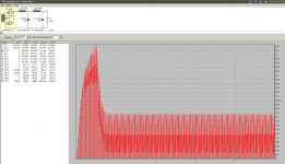
Example PSUD2 at startup.
Assumes 275Vrms trafo and choke resistances of ~30Ω each.
It shows that the current peaks will be >1A when the rectifier is only half-warm. Arc-over is very likely!
Please remember that this model does does take account of the reduced inductance of the chokes at high current.
With a rectifier like GZ34 - where all manufacturers (except Mullard and other old production) have a patchy reliability record - it is worth checking that the current-peaks are much lower than the 750mA specification, during startup.
Attachments
Last edited:
Rod,
I don't know if current production lacks a sufficiently "hard" vacuum or not, but that is 1 possible source of trouble. The series SS diode tweak has an excellent track record for stopping start up arc over. Some time ago, a poster over on AA tried the tweak with a JJ and was pleasantly surprised. That fellow speculated, perhaps, a Zener like effect was occurring. I really don't know the exact mechanism in operation, but the tweak works and that's good enough (IMO).
Rundmaus' zero "sand" requirement requires him to use both a reliable tube and closely follow data sheet notes.
Also agree on the cap reduction. Even on SE amps I usually use 40-50uF.
A cheaper alternative, if you don't want to put SS in, is to use 70s Hitachi 5AR4s. They are rugged and don't cost as much as vintage Mullards. Of course it's been awhile since I bought rectifier tubes so the Hitatchi tubes may not be as easy to get as they used to be.
A cheaper alternative, if you don't want to put SS in, is to use 70s Hitachi 5AR4s. They are rugged and don't cost as much as vintage Mullards. Of course it's been awhile since I bought rectifier tubes so the Hitatchi tubes may not be as easy to get as they used to be.
Anything NOS of note in the 5AR4 dept. will induce serious sticker shock. 🙁  With the SS diode tweak, Sovtek 5AR4s are highly satisfactory. At under $20 each, I would not look further. The OP's zero "sand" requirement brings New Sensor's "reissues" into play. Field reports about the "reissues" are favorable, but they cost substantially more. Draw your own conclusions.
With the SS diode tweak, Sovtek 5AR4s are highly satisfactory. At under $20 each, I would not look further. The OP's zero "sand" requirement brings New Sensor's "reissues" into play. Field reports about the "reissues" are favorable, but they cost substantially more. Draw your own conclusions.Unless you have a good "swinging" choke at the input I would think the choke is going into saturation while the 220uF cap is charging up. Since the inductance falls off the 220uF cap is now a reservoir cap for a short period of time and so too large a value for the wimpy modern production 5AR4.
What model 5H choke is at the input?
What model 5H choke is at the input?
I had exactly this problem when I fired up my 300B monoblocs a few years ago. One of the JJ GZ34s consistently arced over on switch-on. I asked Kevin Kennedy, the designer, for his advice, and he recommended the same solution as Eli did: inserting a UF4007 in series with each anode solved the problem with minimal expense. And yes, I would throw out any rectifier that has arced over.
In this case it wasn't related to excessive capacitance on the anode of the GZ34: in Kevin's design the choke has a 47uF PP cap on each side, which I regard as quite modest.
Alex
In this case it wasn't related to excessive capacitance on the anode of the GZ34: in Kevin's design the choke has a 47uF PP cap on each side, which I regard as quite modest.
Alex
Last edited:
Rod,
I don't know if current production lacks a sufficiently "hard" vacuum or not, but that is 1 possible source of trouble. The series SS diode tweak has an excellent track record for stopping start up arc over. Some time ago, a poster over on AA tried the tweak with a JJ and was pleasantly surprised. That fellow speculated, perhaps, a Zener like effect was occurring. I really don't know the exact mechanism in operation, but the tweak works and that's good enough (IMO).
Rundmaus' zero "sand" requirement requires him to use both a reliable tube and closely follow data sheet notes.
Hi Eli,
There are different two problems under discussion here.
First is the frequently observed peak-inverse voltage failure - which may well be caused by poor pumping or other vacuum defects. These show up in older guitar amps with high B+ voltages, and even Dynas, among other designs. The added series 1N4007 may well fix these, since reverse-conduction is most unlikely with this protection in place.
BUT, the OP's PP1C only runs on 285V dc or so, making this unlikely to be the problem.
OTOH, using 2x 220µF caps will be almost certain to cause overcurrent arc-overs - which is a separate design flaw, caused by violation of IFSM
(peak forward current) rather than VRINV (reverse peak voltage). Adding series diodes will not address IFSM
failures at all. For these faults, the caps must be reduced in size, or the resistance in series with the rectifier increased, or both.
The OP supply with 5H-220µF-5H-220µF will certainly breach IFSM
limit for GZ34, unless the Real part of the complex series-impedance is unusually high.
The data sheet misleads many constructors in power supply design, because it implies that you can draw 250mA from a supply with a 10H choke, and add any old value of C after the choke. When the data sheet was written, that may have been true, since the cost of a 220µF cap meant that nobody would even consider using such a value.
Today, the design process is different. We don't really need the old curves of protecting resistance vs. capacitance and dc current -- we just need to be sure the IFSM rating is observed, and preferably:
- with a margin added for a half-warm heater;
- with another margin for known-to-be-patchy designs like the modern GZ34/5AR4.
PSUD2 helps see the value of IFSM, cycle-by-cycle.
The real choices, IMHO, are low cap values (or high series resistance) with the GZ34, or higher cap values and later-designs of damper diodes (or preferably, SiC diodes).
Anything NOS of note in the 5AR4 dept. will induce serious sticker shock. 🙁
The reissue Tung-Sol and Genalex are better tubes than the Sovtek. The reissue Mullard may be as well but I don't stock it since it's coin based and less popular. As a result I have no experience to share.
Typically the U77 Genalex and 5AR4 Tung-Sol sell for $15 to $20 more than the Sovtek, but they have been nearly 100% bulletproof in service even when used near their limits.
IMHO the JJs are problematic at best!
I'm currently using the garden variety Sovtek with series diodes and keep input capacitance <= 51uF.. So far the small number I have used seem reliable. (I'm still mostly using vintage Mullard GZ34s in my system.) Note also that the maximum allowable capacitance value decreases rapidly as the applied AC voltage and hence rectified DC reach the top of their range. Given the propensity of modern 5AR4 to destruct at the slightest opportunity (read minor design issue) I would keep input capacitor values under the maximum. (I recommend <= 51uF except at the extreme high end of the voltage range where I am more comfortable with something like 22uF) Peak currents must be limited to no more than the recommended value of 750mA, take a good look at the recommended series resistance with increasing voltage.
http://www.mif.pg.gda.pl/homepages/frank/sheets/010/g/GZ34.pdf
I will try and find the graphs (Mullard?) I have about the relationship of winding dcr, input capacitor value, and input voltage. If I succeed I will share them here.
http://www.mif.pg.gda.pl/homepages/frank/sheets/010/g/GZ34.pdf
I will try and find the graphs (Mullard?) I have about the relationship of winding dcr, input capacitor value, and input voltage. If I succeed I will share them here.
Example PSUD2 at startup.
Assumes 275Vrms trafo and choke resistances of ~30Ω each.
It shows that the current peaks will be >1A when the rectifier is only half-warm. Arc-over is very likely!
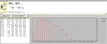
Hi there,
a quick PSUD run with the original values from the circuit shows the current peaks at 550mA, below the 750mA spec:
Besides, the test setup of one channel has worked well and was powered up many times under different conditions, hot, cold, amp load, resistor load, ...
Regards,
Rundmaus
Attachments
Last edited:
Now try the same thing simulating a saturated first inductor with a few mH of inductance and see what occurs.
I would carefully measure the DCR of the transformer primary and HV secondary windings to determine whether they differ and whether or not the secondary DCR meets the criteria in the datasheet I linked to. You can add a small amount of series resistance if necessary in the plate leads.
Also it is not beyond the realm of possibility that most modern 5AR4 do not meet the peak current specification and fail as they approach it. (There seems to be more than a little evidence for this conjecture given how many modern ones fail immediately in circuits where vintage ones survived for decades)
- Status
- Not open for further replies.
- Home
- Amplifiers
- Tubes / Valves
- GZ34 JJ flashover