Hi all, I am trying to finalize my schematic for a standalone guitar preamp based off ceriaton chupacabra. I have implemented the output cathode follower from a soldano X88R and I can't seem to get it to look right in the simulation.
I need the output to be line level (1Vrms) and I do not know what values I should be using for the B+ drop resistors (R1, R2, R3 in the schematic, R11, R30, R32 in the sim) as just messing around with them I cannot get the dc voltages to match what the voltages should be (per ceriatones voltage chart and what I have found in a thread discussing an x88r clone for the output stage)
If anyone could give me some help figuring out where to go from here I would greatly appreciate it.
Attachments
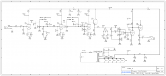
Look at the voltage divider formed by R35-R36 in your sim. That divider sets the output voltage swing from the cathode follower U6.
If you make R35 slightly larger you will see a lower level at the output.
You could make R35-R36 a 100K pot and adjust the output level on a scope connected to the output of C13.
I've did this exact tweek when I set up a Twin Reverb preamp output to drive a big Mac power amp a la Jerry Garcia's rig.
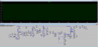
As shown, the level going into V3a is too high and that stage is clipping in your simulation.
The plate voltages shown for V3 cannot possibly be correct; the idle current would have to be only 23µA.
Your simulation doesn't include the zener clipping diodes, which will reduce the output voltage quite a bit. I imagine you'd want it to be able do ~1V RMS with the 12V diodes engaged.
The plate voltages shown for V3 cannot possibly be correct; the idle current would have to be only 23µA.
Your simulation doesn't include the zener clipping diodes, which will reduce the output voltage quite a bit. I imagine you'd want it to be able do ~1V RMS with the 12V diodes engaged.
Adam that is a really good idea, I may do that.
bmc0 I am also starting to think my source for the dc voltages are bogus, at this point I am just going to build it and experiment. also, the zeners are an optional switch in the original design, the middle position omits them from the circuit. From what ive seen the output of the amp does not drop considerably when those diodes are engaged.
bmc0 I am also starting to think my source for the dc voltages are bogus, at this point I am just going to build it and experiment. also, the zeners are an optional switch in the original design, the middle position omits them from the circuit. From what ive seen the output of the amp does not drop considerably when those diodes are engaged.
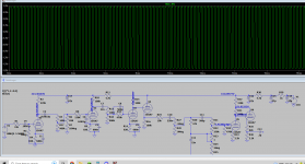
The other voltages are pretty close. With Adrian Immler's 12AX7 model, I'm getting 83V, 179V, and 184V at the plates for V1a, V1b, and V2a, respectively.I am also starting to think my source for the dc voltages are bogus
I don't see how that could be true unless the power amp is clipping. With the preamp driven to heavy clipping, the signal out of the first cathode follower (V2b) is about 95V RMS. With the 12V zeners switched in, the signal drops to about 13V (12V plus the forward voltage); a change of -17dB.From what ive seen the output of the amp does not drop considerably when those diodes are engaged.
I found a few discrepancies between your schematic and the layout from the Ceriatone website:
- The input grid stopper is 33k in the Ceriatone layout, not 27k.
- The input capacitor is 0.0047µ rather than 0.1µ.
- The first 0.001µ cap (immediately after the 0.0022µ coupling cap) is not present.
- The smaller bright caps are 560p instead of 470p.
- The tonestack slope resistor is 47k rather than 100k.
- Treble and mid controls are 250k and 25k (not much of a change, of course).
- The master volume control is before the tonestack (I see you actually did this in the LTspice sim).
Actually now that I think about it, considering the purpose of those diodes are to change the "era" or effectively how much gain the overall amp has I do think you are correct. Those diodes are probably intended just to drop the overall db.bmc0 I don't see how that could be true unless the power amp is clipping. With the preamp driven to heavy clipping, the signal out of the first cathode follower (V2b) is about 95V RMS. With the 12V zeners switched in, the signal drops to about 13V (12V plus the forward voltage); a change of -17dB.
Thank you so much for checking that layout for me I definitely should have done that sooner.
The only question I have left is you say you got 83V on the plate of V1a, How come I only get 53V? I dont know where I found my 12ax7 model and I am very noob to ltspice.
I believe this design is at a point where I will order all the parts (after revising the schematic for the errors you found) and I will just build it and experiment with little tweaks to get it perfect later. Thank you so much for helping me figure this out.
Attachments
Just a different 12AX7 model. Some are more accurate than others.The only question I have left is you say you got 83V on the plate of V1a, How come I only get 53V?
It should be possible to significantly reduce the level change with the different 'era' settings by switching between different resistors (as part of a voltage divider) along with the diodes.
One other minor discrepancy: the grid stopper on the first stage should be after the grid leak. Doesn't really make much difference, but I thought I'd mention it.
- Home
- Live Sound
- Instruments and Amps
- guitar preamp simulation