Greetings:
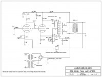
I have been building, and rebuilding and rebuilding this GU32/832 beam tetrode based 5 watt amp. I've make it as point to point, bread board and even made pcbs. The result is consistently very low audio output that is unchanged by adjusting the pot. I know that it is a fairly simplistic circuit but it is completely kicking my butt. I would greatly appreciate it if someone could look at the schematic and see if there are any obvious (to you) discrepancies that I am missing. Thanks.
I have been building, and rebuilding and rebuilding this GU32/832 beam tetrode based 5 watt amp. I've make it as point to point, bread board and even made pcbs. The result is consistently very low audio output that is unchanged by adjusting the pot. I know that it is a fairly simplistic circuit but it is completely kicking my butt. I would greatly appreciate it if someone could look at the schematic and see if there are any obvious (to you) discrepancies that I am missing. Thanks.
Attachments
Whatever fault you may/may not have, the audio should certainly be alterable via the pot. If the audio really is unchanging as you turn the pot to minimum volume then you have a basic wiring problem in that area for starters.
Also check the DC conditions of all the stages making sure that all are drawing the correct current.
Also check the DC conditions of all the stages making sure that all are drawing the correct current.
Nothing jumps out at me. Suggest you post DC voltage measurements at all tube electrodes. What test gear is available? Is the OPT new or used? What is your signal source?
Truly, no change when adjusting the pot. I put a jumper across the pot and still the same.
As far as test gear, minimal; I have a multimeter and a capacitance tester.
The OPTs are new Edcors.
The signal is from an iphone at this point.
As far as test gear, minimal; I have a multimeter and a capacitance tester.
The OPTs are new Edcors.
The signal is from an iphone at this point.
Voltages:
286.8v - B+ after the cap
22.5v - GU32 pin 4
260.7v - after the 3k3 resistor
68.6v - at 12at7 pin 1
17.3v at 12at7 pin 3
0.82v - at 12at7 pin 8
16.2v - at 12at7 pin 6
286.8v - B+ after the cap
22.5v - GU32 pin 4
260.7v - after the 3k3 resistor
68.6v - at 12at7 pin 1
17.3v at 12at7 pin 3
0.82v - at 12at7 pin 8
16.2v - at 12at7 pin 6
Looks like multiple problems. Suggest you write 12AT7 pin numbers from the datasheet on the schematic and recheck its hookup. Also check voltage downstream of the 4K7 resistor and confirm correct resistor values (after discharging the power supply completely). You have tried more than one 12AT7, correct?
Hi,
I have also built the amplifier based on the circuit above - i can confirm that the curcuit works with the values that is shown in original circuit.
I tried a variety of tubes - 6n1p, 6n2p etc. - it works even withaut any adjustment of resistor values (of course its better to adjust cathode /anode resistors according to tube parameters) At the end I chose 6n23p which also works fine with standard values. I think that there are errors in assembly or the tubes are damaged ... and of course grid stopper resistors should be placed close to the grids of gu32. Old gu32 from ..tend to lose vacuum..i have 20 nos gu32 from 50ties in boxes and some of them weak or even whith white glass...i hope it will helps you.
when i build amp, this is the sequence i follow:
1. mount all parts...
2. wire power traffo switching (on/off)
3. wire the filaments, then check to see all tubes light up....
4. wire the psu and components, then check for voltage to see if they add up,
take note that psu unload will have higher voltages, but since your
filaments are drawing power, maybe not so much but still higher that when the amp is running normally, the thing to watch out is overvolting the power supply caps.
5. wire the output stage, opt and the voltage amps. do not yet connect the feedback line..
6. when powering up, check the plate and cathode voltages to see it they are close to
what the schematic shows...
7. then connect your speakers, when you touch the top of the volume control
you should hear loud hum...\
8. once confirmed, connect your feedback line, if the amp sequels, reverse the connection of the feedback to the other side of opt secondary....
Got it working this afternoon! I found two ground issues and went through 6 GU32s before I found 2 that worked. Thanks to all for the much needed advice.
 thanks for the update.
![IMG_0915[1].jpg](/community/data/attachments/550/550462-52834a5ff88e24bcd2ede4fea2ab046d.jpg?hash=UoNKX_iOJL)
- Status
- Not open for further replies.
- Home
- Amplifiers
- Tubes / Valves
- GU32 Push Pull amplifier Troubleshooting