There are numerous photos of this model on the web, - go to
Grundig Satellit 3400 und der BFO / SSB Knopf – DL2YMR s Blog
Grundig Satelit 3400 Professionell lässt sich einschalten aber es kommt kein Mucks, Hifi-Klassiker - HIFI-FORUM
FM problem on Satellit 3400 - UK Vintage Radio Repair and Restoration Discussion Forum
GRUNDIG Satellit 3400 professional KW MW SW UHF UKW Empfanger
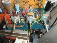
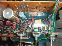
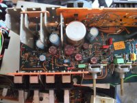
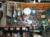
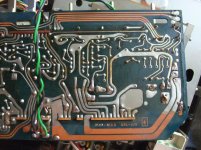
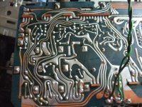
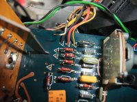
but not of the power supply + amplifier unit alone when it is in dismantled condition. This images I have upload here.
To remove this unit from this device, numerous steps must be observed that are not described in detail in the service manual - go to
GRUNDIG SATELLIT-3400 SM Service Manual download, schematics, eeprom, repair info for electronics experts
Therefore it was very difficult for me, among other things due numerous cables that have to be unsoldered and because of the very tight space available.
With the help of a second device of the same model, I succeeded.
After removing some contact issues at the variable resistors and assemble of the PS/amp unit there was at both devices still to observe a more or less effective contact resistance in the signal path (variation of output level similar like on a defektive volume control pot - both on FM and AM-ranges).
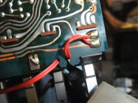
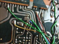
After long search I note, reason therefore is a crack of conductor track (at both devices of this model) between 15m and 19a of StV301 (push-button switch assembly.
To avoid dismantling the entire device (to get to the soldering side of the main board), a cable connection was simply soldered between the soldering connections 15m and 19a of StV301.
Are there anywhere pictures on the web from a completely dismantled device of this model and the associated steps of this process ?
Best thanks for posting an URL.
Grundig Satellit 3400 und der BFO / SSB Knopf – DL2YMR s Blog
Grundig Satelit 3400 Professionell lässt sich einschalten aber es kommt kein Mucks, Hifi-Klassiker - HIFI-FORUM
FM problem on Satellit 3400 - UK Vintage Radio Repair and Restoration Discussion Forum
GRUNDIG Satellit 3400 professional KW MW SW UHF UKW Empfanger
but not of the power supply + amplifier unit alone when it is in dismantled condition. This images I have upload here.
To remove this unit from this device, numerous steps must be observed that are not described in detail in the service manual - go to
GRUNDIG SATELLIT-3400 SM Service Manual download, schematics, eeprom, repair info for electronics experts
Therefore it was very difficult for me, among other things due numerous cables that have to be unsoldered and because of the very tight space available.
With the help of a second device of the same model, I succeeded.
After removing some contact issues at the variable resistors and assemble of the PS/amp unit there was at both devices still to observe a more or less effective contact resistance in the signal path (variation of output level similar like on a defektive volume control pot - both on FM and AM-ranges).
After long search I note, reason therefore is a crack of conductor track (at both devices of this model) between 15m and 19a of StV301 (push-button switch assembly.
To avoid dismantling the entire device (to get to the soldering side of the main board), a cable connection was simply soldered between the soldering connections 15m and 19a of StV301.
Are there anywhere pictures on the web from a completely dismantled device of this model and the associated steps of this process ?
Best thanks for posting an URL.
Attachments
-
 DSCF7601.jpg1,021.2 KB · Views: 361
 -
 DSCF7599.jpg1 MB · Views: 361
 -
 DSCF7596.jpg1,020.2 KB · Views: 298
 -
 DSCF7597.jpg1 MB · Views: 303
 -
 DSCF7594.jpg1 MB · Views: 310
 -
 DSCF7590.jpg1 MB · Views: 335
 -
 DSCF7589.jpg1 MB · Views: 378
 -
 DSCF7587.jpg997.9 KB · Views: 244
 -
 DSCF7584.jpg1,020.5 KB · Views: 259
 -
 DSCF7581.jpg999.2 KB · Views: 298
Last edited: