I assume a ground loop is a very low signal, and that the problem occurs when you amplify said signal.
If correct, then a heater circuit could live on the chassis side of a ground disconnect network (diodes and thermistor), right?
Or can even the low-level ground loop signal transfer through the heater to the signal being amplified?
Thanks,
Jeff.
If correct, then a heater circuit could live on the chassis side of a ground disconnect network (diodes and thermistor), right?
Or can even the low-level ground loop signal transfer through the heater to the signal being amplified?
Thanks,
Jeff.
A ground loop is a loop (i.e. multiple connection) in the grounding arrangements. If any AC magnetic field links to this loop then a voltage will be induced, so points connected together by a piece of wire will not be at the same potential. This extra signal can get into the circuitry, as it often appears in series with the wanted signal.
I have never heard of using a thermistor as part of a ground breaker. It sounds dangerous.
A heater circuit can be connected to the chassis, although normally it would be referenced to somewhere on the circuit. Hum can get from a heater circuit to the audio circuit. There are three common routes:
1. heater-cathode leakage in valves - minimise by buying good quality valves and adding a DC bias to the heater circuit, also by grounding the cathode directly (on input stages)
2. capacitive coupling - minimise by twisting the heater wires and keeping them well away from signals
3. inductive coupling - minimise as for capacitive coupling
Valves/tubes that operate at an elevated voltage can require the heater circuit to be elevated to a similar high voltage.
A floating heater winding can be tapped into an elevated reference voltage to allow this to operate without overstressing the valve/tube.
Do not willy nilly take a heater winding to Chassis without knowing what the valve/tube requires.
A floating heater winding can be tapped into an elevated reference voltage to allow this to operate without overstressing the valve/tube.
Do not willy nilly take a heater winding to Chassis without knowing what the valve/tube requires.
It's a Bottlehead S.E.X. in question. The heater circuit is +/- 4.4V DC (centred around ground via a pair of resistors).
The entire kit uses the chassis as ground (signals, heaters, transformer casings, etc.), with no disconnect network. I'm thinking of adding a disconnect, and was wondering which side of it the heaters should be on. It sounds like the answer is on the signal side.
It's fairly common in Nelson Pass designs. Do tube guys more often use an RC network over a pair of diodes? Or something else?
The entire kit uses the chassis as ground (signals, heaters, transformer casings, etc.), with no disconnect network. I'm thinking of adding a disconnect, and was wondering which side of it the heaters should be on. It sounds like the answer is on the signal side.
... I have never heard of using a thermistor as part of a ground breaker. It sounds dangerous.
It's fairly common in Nelson Pass designs. Do tube guys more often use an RC network over a pair of diodes? Or something else?
I'm thinking of adding a disconnect
So is the circuit hummy now?
If your heaters are on DC now, it is not likely they are involved in a ground loop.
Using the chassis as a ground conductor for signal purposes is poor design. It was common in the 1950s, but there is no excuse for this nowadays. If it really does this then you cannot add a ground breaker.
However, it is much more likely that it does not do this but just grounds the chassis for safety reasons. In that case a ground breaker may prevent hum due to a ground loop. What makes you think you have a ground loop? DC heaters do not cause hum, unless the heater PSU is poorly designed.
You need to tell us much more, otherwise we are all just playing Chinese whispers.
The circuit isn't built yet, so it's definitely not hummy at present. 😉
I'll need to machine my custom case to fit a ground disconnect network though, so I'd rather do it before it's assembled than have to knock it all back down.
I'm not sure it's fair to say the kit uses the chassis for a ground conductor, as there are point-to-point wires between the components and the PSU 0V. However, those wires are also connected directly to the chassis. That's what I'd like to change in my build.
There should be one and only one wire between the audio circuit and the chassis. This wire may be replaced by a ground breaker, if you have hum and are happy to compromise safety to get rid of the hum. As you will already have a connection point on the chassis and the circuit for this wire I cannot see how the chassis will need to be changed to accommodate something else joining these two points instead of a wire.
Some designs use a bolt on the chassis with lots of solder tags attached as a 'star ground'. This is popular but a bad idea. You lose control of where the ground currents go, and you cannot easily insert a ground breaker if it proves necessary. I suspect that people who use such ground tags are secretly thinking that ground is some sort of dumping ground for unwanted currents.
Some designs use a bolt on the chassis with lots of solder tags attached as a 'star ground'. This is popular but a bad idea. You lose control of where the ground currents go, and you cannot easily insert a ground breaker if it proves necessary. I suspect that people who use such ground tags are secretly thinking that ground is some sort of dumping ground for unwanted currents.
The enclosure/chassis is not part of the audio circuit.
It is there to protect you from the circuits inside.
It is there to attenuate external interference.
The audio circuits will work without an enclosure. That's often the way we test our prototypes.
Only after we have proved that all the circuits work do we install inside an enclosure. Valve/Tube assemblies could be different, in that the enclosure supports the valve bases.
Then we add in some protection when the equipment is mains powered:
a.) The Protective Earth (PE) wire is permanently connected to the chassis/enclosure.
b.) All exposed conductive parts are connected to the protected chassis.
Ground loop ac can be massive.
Especially if there is a lot of gain in the circuit amplifying the ground loop volts.
I designed a USB mixer with onboard power supply.
I naively just mixed all the power supply grounds and audio ground together.
With the input shorted I got 1VAC hum on the output.
The smoothing capacitor charging impulses modulated the ground and injected noise into the audio.
I redesigned the pcb with power supply kept separate and there was almost zero hum.
Star grounding is vital.
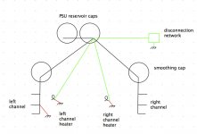
I've drawn a picture of the grounds as specified in the instructions (black and red). I'm proposing to remove the red, and add the green.
(Not shown, but the chassis will of course be connected directly to the mains earth. All the transformer and choke housings will remain connected directly to the chassis.)
I don't plan on a ground breaker, but rather a ground disconnection network. I thought the whole purpose of the disconnection network was to not compromise safety?
(Not shown, but the chassis will of course be connected directly to the mains earth. All the transformer and choke housings will remain connected directly to the chassis.)
There should be one and only one wire between the audio circuit and the chassis. This wire may be replaced by a ground breaker, if you have hum and are happy to compromise safety to get rid of the hum. ...
I don't plan on a ground breaker, but rather a ground disconnection network. I thought the whole purpose of the disconnection network was to not compromise safety?
Attachments
The tube amplifies whatever it sees as a voltage difference between grid and cathode. If that's the program signal, then it amplifies that. If that's hum induced from small fluctuations of the ground plane voltage (hum) due to ground currents, then the tube amplifies that.
In other words, using the chassis as circuit ground may not actually put the chassis at the same ground potential at all spots on the chassis because of currents flowing through and around the chassis. All the tube sees is a slight voltage variation (hum) between grid and ground and so it amplifies it.
One way to prevent or at least minimize this type of induced hum is for a given stage, wire the grid ground reference to the same point as the cathode ground reference for that stage. That way those two parts of the tube are at the same ground potential with respect to each other, even though other parts of the ground circuit may be at slightly different potentials. Therefore there is no voltage difference in ground potential at that point and therefore no ground loop induced hum for that stage can possibly exist.
That is not to say that you should use one gigantic star ground for the entire amp. That doesn't typically produce the quietest results either, and isn't the easiest to manage anyway. I tried it once though, just to experiment. The wiring was a fiasco (a rat's nest of ground runs), and although the amp wasn't terribly noisy, it wasn't all that quiet either.
Your diagram is showing 4 connections to the chassis/enclosure.I've drawn a picture of the grounds as specified in the instructions (black and red). I'm proposing to remove the red, and add the green. <snip>
The disconnection network goes to chassis/enclosure. This is your safety connection.
All the others are return routes for other signal currents.
All these return routes must return their signal current to their own source.
....
All these return routes must return their signal current to their own source.
Cool; I think I've got that down with one exception. Here's the heater circuit:
In this case we're not really returning anything to the source, but rather referencing ground so the heater is +/- 4.4V. I guess the question is +/- 4.4 relative to what, and the only thing that would matter is "relative to the tube signal 0V". So this one should go to the B+ reservoir cap ground, yes?
Attachments

Actually, it is returning the filament current back to the source. The connection from the negative side of the 10000 uF cap goes to the negative side of the bridge. That is the return path--going directly there via its own wire connection, and not using some other ground path to get there.
The entire circuit is referenced to ground via the two 220R resistors. Connect that ground reference to your B+ ground.
The entire circuit is referenced to ground via the two 220R resistors. Connect that ground reference to your B+ ground.
Kward has got it right.
The Current comes from the Source (PT7) and MUST return to the Source (via PT9).
If there is any variation in that current, then it will emitt EMI.
That variation in current can be hum and/or noise and/or interference, anything is not constant DC.
To minimise the EMI, the LOOP AREA of the Flow and Return routes should be minimised. This is easily achieved by using a twisted pair.
Last edited:
Thanks for the extra info, guys.
The kit does contain twisted pair for the heater current path (transformer to rectifiers, rectifiers to filter cap, and filter cap to tube sockets).
It's only the ground reference via the two 220R resistors that needs attention (as it's connected to the B+ ground via the chassis). I'll move that to the B+ reservoir cap via a wire.
No. Good grounding is vital. Star grounding is a way to get grounding which is not too bad without having to think very much; in many cases it is good enough.nigelwright7557 said:Star grounding is vital.
A piece of wire is the safest option. Anything else is less safe, but hopefully better than no connection at all.JeffYoung said:I don't plan on a ground breaker, but rather a ground disconnection network. I thought the whole purpose of the disconnection network was to not compromise safety?
I haven't built as many amps as a lot of folks here. But I have built a variety, including SS amps (both on perf board and PCB's), tube amps (including DHT's), and hybrids. I've used ground lift's (anti-parallel diodes/resistor/film cap), with the diodes sized to handle much more current than the mains fuse.
Every amp has been tweaked after the initial build, and most have been tweaked multiple times. Part of that process has included careful analysis of the ground paths and inductive coupling. In every instance I've been able to eliminate the ground lift.
I have no tolerance for hum (if I can hear it a foot from the speaker, it's too much). My obsession on eliminating hum is because I'm not much of an EE, but it is one factor that I can engineer. My main system is at least 100 dB sensitive and comprises 9 separate channels of amplification (which requires some attention to the mains power connections as well).
Sheldon
- Status
- Not open for further replies.
- Home
- Amplifiers
- Tubes / Valves
- Ground loop hum question