Hi,
almost any MI amplifier that is available commercially uses it's chassis as signal ground. Commonly all input and output jacks are mounted directly to the chassis, without isolation. The chassis is earthed through the PE lead. If we connect an external unit that also is earthed to the FX loop (if present), we'll inavoidably have a ground loop.
To cure this issue, I'd still connect the chassis to PE, but isolate signal ground from it via a ground loop breaker (big rectifier bridge with 100 nF across). Are there any (mainly safety) caveats against this idea?
Best regards!
NoHi,
almost any MI amplifier that is available commercially uses it's chassis as signal ground.
Unless very poor design all have their own ground path for the circuit itself, and it´s connected at only one point to chassis and safety ground.
No, for decades now.Commonly all input and output jacks are mounted directly to the chassis, without isolation.
Yes.The chassis is earthed through the PE lead. If we connect an external unit that also is earthed to the FX loop (if present), we'll inavoidably have a ground loop.
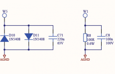
Just one variation on what Marshall does.To cure this issue, I'd still connect the chassis to PE, but isolate signal ground from it via a ground loop breaker (big rectifier bridge with 100 nF across). Are there any (mainly safety) caveats against this idea?
Many use something similar.
You are real close 🙂
Attachments
My Dean Markley has a ground lift.
I have the correct schematics but it's not shown. Perhaps not surprising. It does help with hum at high gain to some degree.
I have the correct schematics but it's not shown. Perhaps not surprising. It does help with hum at high gain to some degree.
I've been speaking of classic Fender's, Marshall's and Hiwatt's, for instance 🙄!
And the aim is to avoid ground loops when designing a new amplifier.
Best regards!
And the aim is to avoid ground loops when designing a new amplifier.
Best regards!
There’s a lot of info on the web about grounding Fender amps. Beware and make sure you don’t do something dangerous. Hoffman had good info on rewiring the bandmaster circuit for better ground potentials. You can isolate the 1/4” jacks and wire the ground to the cathode resistor/cap or Preamp section ground bus.
For example, this may help
https://el34world.com/Hoffman/files/Hoffman_5F6A.pdf
I feel like ranting on acronyms but i’ll Ask what is PE and MI?
Ground lifting is more appropriate with balanced lines
For example, this may help
https://el34world.com/Hoffman/files/Hoffman_5F6A.pdf
I feel like ranting on acronyms but i’ll Ask what is PE and MI?
Ground lifting is more appropriate with balanced lines
Last edited:
> what is PE and MI?
Protective Earth (what we call the green/bare wire).
Musical Instrument (division of companies who make many types of audio).
Protective Earth (what we call the green/bare wire).
Musical Instrument (division of companies who make many types of audio).
Marshall plan looks like it's optimally optimised for mass production.
Elliot's plan with a 30A brick bridge looks better for a DIYer - and can be soldered PTP onto the bridge leads (or fastons; even better) and then screwed onto the chassis, neatly.
Elliot's plan with a 30A brick bridge looks better for a DIYer - and can be soldered PTP onto the bridge leads (or fastons; even better) and then screwed onto the chassis, neatly.
I’m not in favor of “GROUND LIFT” as it is a deadly disaster in the making.
Fix the problem and keep the “SHOCK HAZZARD” safety fully working.
First find the real problem and apply a safe solution.
I do realize that the following is not a super detailed DIY, as it is intended as a basic plan.
I have several things that I use to help find out what the real problem is.
1. Small plastic AM battery radio. Look for NOISE
2. Inductive loop pickup (Guitar pickup) on a 3’ wooden stick connected to a band limited amplifier (BW 500Hz) connected to a headphone. Looking for HUM FIELDS.
3. 50/60 Hz noise current source of 12 volts @ 100ma. This is to inject current into the ground of an amplifier/mixer or DUT. To look for correctly grounded amplifier.
I use a BALANCED CONNECTION from the guitar to the instrument amplifier. This keeps the ground currents out of the signal path. Modify guitar for TRS jack and use the pickup coil only connected to T&R, the shield on the pickup, pot frame(s) and any other shielding connected to the S, New TRS cable to amplifier. Modify amplifier input connector to TRS and wire R lead back to the input stage return.
If all is done correctly then when applying the NOISE CURRENT to the inputs & or guitar you will not have hum pickup.
Good Hunting Duke
- Status
- Not open for further replies.
- Home
- Live Sound
- Instruments and Amps
- Ground lift in a guitar amplifier?