Hi everyone,
I’m working on a custom audio build that combines an R2R DAC, an Aleph 1.7 preamp, and a power amplifier inspired by the Dartzeel NHB-108, all inside the same chassis.
Given the mix of digital, analog, and power circuitry, I’m trying to carefully plan the grounding strategy to avoid ground loops and noise. I’ve labeled every GND point in my design and created a PDF diagram showing all connections, supplies, and ground references. Each GND is numbered to make it easier to follow.
🔧 What I’m asking:
I’d really appreciate some help figuring out:
• Which GNDs should be connected together?
• Where should the central ground (star ground) be placed?
• Which GNDs (if any) should be isolated (e.g. digital vs analog)?
• How to properly handle speaker return ground in this context?
The PDF diagram is attached to this post.
Any suggestions or guidance would be hugely appreciated!
Thanks!
Daniele
Attachments
Some common types of 'ground', note that each has a different task:
1] Safety Ground/Protective Earth
2] Chassis
3] Shield
4] DC supply common
5] Audio circuit common
6] Digital circuit common
7] Phantom supply common
1] Safety Ground/Protective Earth
2] Chassis
3] Shield
4] DC supply common
5] Audio circuit common
6] Digital circuit common
7] Phantom supply common
i would make a star with all the psu 0v's and then take off a spur to form a buss ground to supply the various boards etc.
no loop breaker unless it is needed.

no loop breaker unless it is needed.
I would connect each DC supply common to each of it's appropriate circuits common.

I2SoverUSB tends to sound better to most people if run from two clean, mutually isolated 5v supplies. The default is that the dirty USB side will run on USB power, which some people find to sound rather bad. Obviously that has to be because the galvanic isolating between clean and dirty does not prevent radiated EMI/RFI coupling between the clean and dirty sides. Also, USB boards can be substantial emitters of radiated EMI/RFI noise that can couple into dac boards. Thus some physical isolation and or separation of the USB board from the DAC board can be helpful, although care has to be taken for avoiding excessively long I2S wiring. Reclocking I2S signals (or whatever signal clocks the dac output, which in some could be MCLK/2) just before the I2S signals go into the dac can produce some audible improvement if done properly. However, for best results that may require external clocking of the USB board (which I2SoverUSB does support)....the USB/I2S board (JLSounds) has fully isolated connections.
Also, I2SoverUSB should be on mutually isolated 5v power relative to RPi, which is a conducted and radiated EMI/RFI source.
As indicated in #6, power supply grounds should only be connected together at the load boards. Also, shared grounds, such as with +-48v power supplies should be avoided duo to "shared impedance coupling distortion" effects. Instead only connect +48v and -48v supply grounds at the load board. That means no center tapped power transformer secondaries should be used, instead use a separate isolated power supply secondary winding for each isolated power supply.
Beyond the above, to some extent it depends if all the boards and power supplies shown in the schematic will be in one single metal case, or in multiple cases.
Last edited:
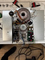
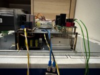
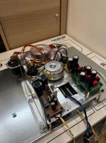
The enclosure will house all the components. I have three toroidal transformers and one switching power supply.
The first toroidal has two secondary windings for the ±48V rails.
The second has two secondary windings to generate 5V and 3.3V.
The third transformer powers the preamp directly.
The switching PSU powers the Raspberry Pi and the USB input section of the JLSound board.
I’m attaching a photo so you can get a better idea of the setup.
Attachments
Using SMPS for I2SoverUSB dirty side will probably (almost certainly) adversely affect sound quality. Some people have already tried it, and the consensus seems pretty clear that clean power on the dirty USB side is preferred.
Unfortunately, I only have one Salas L-Adapter and one 5V switching power supply.
I could power the “dirty” side of the JLSounds board through the USB connection; otherwise, the only alternative would be the switching supply.
I could power the “dirty” side of the JLSounds board through the USB connection; otherwise, the only alternative would be the switching supply.
You show the negative side of the -48 supply grounded??? Probably a mistake.
I would recommend connecting grounds the same path as the signal path, and supply grounds directly to their respective loads. Avoid any wire that is both a signal path and a power supply path. But be sure the speaker return goes directly to the +/-48V supply(s), not through the power amp module.
I would recommend connecting grounds the same path as the signal path, and supply grounds directly to their respective loads. Avoid any wire that is both a signal path and a power supply path. But be sure the speaker return goes directly to the +/-48V supply(s), not through the power amp module.
Is there an order on the "comb" (the ground bus) for the various devices to be linked to?i would make a star with all the psu 0v's and then take off a spur to form a buss ground to supply the various boards etc.
no loop breaker unless it is needed.
View attachment 1448268
I remember a similar ground configuration on a blog teaching how to assemble the LM3886 Gainclone amplifier.
I would not use a central "star" ground.
If I was building it, I would take the voltage and ground wires from each power supply , tightly twist them together, and connect them directly to the power consumer.
For instance, for the 5V supply which powers two boards, I would take two pairs of twisted wires and connect them to the two boards.
For the 3.3V supply, one twisted pair to the one board.
For the +/-48V supply, one twisted bundle to the one board.
Then from each power supply ground, one wire from each to the ground loop breaker to chassis.
Familiar with "shared impedance coupling?" Its a good way to cause distortion. Each power supply output, say +48v, should have its own dedicated ground wire that only connects to ground at the load board where the +48V is used. Otherwise you get ground currents from multiple power supplies flowing in the same wires. Each ground current causes its own voltage drop across that wire. The voltage drops all add up and effectively modulate all the power supply rail voltages which then produces distortion. Beyond that there is no reason to create ground loops. Grounds follow signals from board to board. Then at the output board that will connect to external user equipment, connect a hum breaker circuit from the ground on that board to the AC line ground (which is done for safety, and to help minimize ground-conducted noise). If there is an input board with external connections, then maybe consider another hum breaker for it.
If considering other schemes, I would at least suggest to start with the above, see how it sounds. Then see if changing it to something else can work without hurting the sound. Safety of course has to be first consideration, but hopefully safety can be accomplished with minimal ground loops and with minimal loop areas.
If considering other schemes, I would at least suggest to start with the above, see how it sounds. Then see if changing it to something else can work without hurting the sound. Safety of course has to be first consideration, but hopefully safety can be accomplished with minimal ground loops and with minimal loop areas.
Last edited:
Is there an order on the "comb" (the ground bus) for the various devices to be linked to?
in order of current, heavier to left, going down towards the right.
- Home
- Design & Build
- Electronic Design
- Ground connection