Thoughts? for a 50V bias Ohm's law says 0.0025A. This seems like a long battery life if it's switched with power.
I know I can used fixed resistors around the pot for more fine tuning BTW
And this is only valid for a design with minimal grid current.
I know I can used fixed resistors around the pot for more fine tuning BTW
And this is only valid for a design with minimal grid current.
Attachments
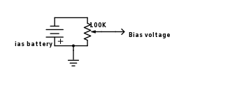
What you show resembles common "fixed" bias power O/P tubes. The difference is a battery, instead of a rectified AC rail.
The grid to ground resistor connects to the trim pot.'s wiper. Don't forget the DC blocking cap. to which the driving signal is applied.
The grid to ground resistor connects to the trim pot.'s wiper. Don't forget the DC blocking cap. to which the driving signal is applied.
Thoughts? for a 50V bias Ohm's law says 0.0025A. This seems like a long battery life if it's switched with power.
I know I can used fixed resistors around the pot for more fine tuning BTW
And this is only valid for a design with minimal grid current.
What battery would you use?
That's exactly my question too. Those old "high voltage" carbon batteries are virtually impossible to find today. And 30 penlight cells in series is awful impractical. Assuming the rest is run from a power transformer that has no bias tap, buy a cheap little 12V filament transformer and run it backwards from a 6V filament line. This will give you around 60 volts on the primary (which is now the secondary). Bridge rectify that and your good to go with a lot less cost and space.What battery would you use?
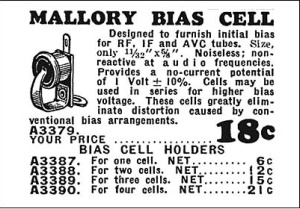
In the ***old*** days (think 20´s and 30´s , not frickin´Nuclear and Space Age 40`s and 50´s 😉 ) bias batteries were the way to go, you pick the value you need and use it:

Earliest stuff used tiny "bias cells" which looked like tiny flying saucers, go figure:

Earliest stuff used tiny "bias cells" which looked like tiny flying saucers, go figure:
That's exactly my question too. Those old "high voltage" carbon batteries are virtually impossible to find today. And 30 penlight cells in series is awful impractical. Assuming the rest is run from a power transformer that has no bias tap, buy a cheap little 12V filament transformer and run it backwards from a 6V filament line. This will give you around 60 volts on the primary (which is now the secondary). Bridge rectify that and your good to go with a lot less cost and space.
https://en.wikipedia.org/wiki/A23_battery
I was thinking these...
5 in series make 60V
Last edited:
What if you went half battery bias without the pot, and half cathode bias to get the auto bias.
For example use 3, 9 volt batteries for 27 volts and a cathode bias resistor for the rest.
I do that for an 845 SE amplifier and do not have to worry about changing the bias battery.
For example use 3, 9 volt batteries for 27 volts and a cathode bias resistor for the rest.
I do that for an 845 SE amplifier and do not have to worry about changing the bias battery.
That form of battery biasing would be far more likely to fail - ending in tears no doubt - as there are so many cell interconnects that need to work, and a big sign on the amp power switch saying 'check the battery first before turning on' and 'replace battery every year' (as per a smoke alarm detector application - which is a subtle pun on the consequences to the amp).
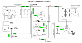
This reminds me something I allways wanted to ask! The attached schematic is from Troels Gravesen's website. I hope it's OK posting it here. Please read more about it here: TRAM w.
The idea is to place the battery in series with the grid so no current -or very little- will flow through it. In this application it is used to bias a small signal tube. For a power stage fixed bias we need something adjustable but the pot on the battery defeats the operation principal, so could it be done with a pot on the cathodes?
What do you thing of this in general?
Attachments
This reminds me something I allways wanted to ask! The attached schematic is from Troels Gravesen's website. I hope it's OK posting it here. Please read more about it here: TRAM w.
The idea is to place the battery in series with the grid so no current -or very little- will flow through it. In this application it is used to bias a small signal tube. For a power stage fixed bias we need something adjustable but the pot on the battery defeats the operation principal, so could it be done with a pot on the cathodes?
What do you thing of this in general?
If you put the battery on the cathode it will charge when the amp is turned on so you can't use a primary cell.
Those old "high voltage" carbon batteries are virtually impossible to find today.
They are still made by specialized industrial battery manufacturers and you can buy it on Amazon.com (as example - search: Exell battery). They use alcaline cells now. The battery comes in a blank industrial case, ready to be covered by a paper replica of a vintage battery. Those batteries are super expensive, of course. The price of the 67.5v battery (the popular 457/467 type) is more than 50 USD; the 45v model 455 is a little cheaper.
What I mean is batteries on the grids and resistors -pots- on the cathodes.If you put the battery on the cathode it will charge when the amp is turned on so you can't use a primary cell.
This reminds me something I allways wanted to ask! The attached schematic is from Troels Gravesen's website. I hope it's OK posting it here. Please read more about it here: TRAM w.
The idea is to place the battery in series with the grid so no current -or very little- will flow through it. In this application it is used to bias a small signal tube. For a power stage fixed bias we need something adjustable but the pot on the battery defeats the operation principal, so could it be done with a pot on the cathodes?
What do you thing of this in general?
Bias current is defined in the cathode circuit. you could throw a battery in the cathode circuit. However, you would go by the rules of self bias for the voltages instead of fixed bias.
Batteries do make interesting coupling caps btw.
Self bias is interesting adventure in output tubes. An interesting SE amp could be made by a 12ax7 and a EL34 @150V B+. the cathode circuit of the el34 is the 12 ax7 heater (in 12 v operation) yielding a bias current of around 150mA.
If you use a battery in the cathode circuit it must be rechargeable though 🙂
I have an out push pull that uses ECL82 with 12AX7 heater as the bias. Free Power of sorts...
I use A23 and AA batteries for bias in variety of designs, but generally try to use them in places where the battery has a specific benefit - for example in a floating application or where there is no negative supply, and the voltage and currents (essentially a uA or less) are within the range of cheaply available batteries.
In the sort of application you propose a conventional bias supply is more practical and lower risk.
In the sort of application you propose a conventional bias supply is more practical and lower risk.
I use A23 and AA batteries for bias in variety of designs, but generally try to use them in places where the battery has a specific benefit - for example in a floating application or where there is no negative supply, and the voltage and currents (essentially a uA or less) are within the range of cheaply available batteries.
In the sort of application you propose a conventional bias supply is more practical and lower risk.
#1 There is only 300V available, and a negative grid bias makes more efficient use of it.
#2 I'm not concerned with the risks per se as I use a CCS in the cathode in case the batteries fail. And to me using 4 A23 batteries in series across a pot is far more simplistic than a bias supply (Unless somebody knows of a negative equivalent to a TL783). It's much smaller, and doesn't need much (like none, right?) filtering either.
I've been running 3 9V (-27V) batteries in the grid circuit of the power tubes with a CCS set at 70 ma in the cathodes. Since there is no adjustment they are connected all the time. So far they haven't lost 0.01V but I know that connecting them across a pot will draw current. In this amp the only way to get negative power that I know of would be a B- of -300V, not cool.
I have used series strings of 5 each, or series strings of 6 each 9Volt alkaline batteries. They are about 9.5V per cell, so that was -47.5V and -57V grid bias.
I used matched output tubes, and adjusted the B+ to get the plate current that I wanted.
A typical circuit was:
Plate of the Driver tube connected to a Coupling Cap.
The other end of the Coupling Cap connected to a junction of: The grid 220k Ohm return resistor, and The (+) end of the series string of 9V batteries. The other end of the grid return resistor was connected to ground.
The (-) end of the series string of 9V batteries was connected to a 1k Ohm grid stopper resistor, and the other end of the grid stopper resistor was connected to the output tube control grid.
It should be noted that if the tubes have very low grid leakage current, the only significant battery current is during 2 events:
1. Power-on amplifier warm-up (a very brief charging of the coupling cap).
2. Music Volume turned too high, causes clipping of the amp (and sounds bad, as does most all clipping).
It also should be noted that the only significant grid currents listed above, actually very lightly "charges" the battery, it does not discharge the battery.
I have only had to replace the batteries after a few to several years of service.
They do not discharge at the faster rate, as when some users connect a potentiometer across them.
Last edited:
I use various methods, depending on the need, and the parts I have at hand, or parts I have to order.
1. I can adjust B+ by changing the input capacitor before the input choke.
Example, a 1, 2, 3, or 4 uF cap in front of a 20Henry choke.
The larger capacitance has a higher B+ output.
Caution: I calculate the resonance of the first cap and the choke so that it is not resonant at the line frequency, or multiples of that line frequency.
1uf and 20Henry is resonant at about 36 Hz.
0.5 uF and 20Henry is resonant at about 50Hz; that would not be a good idea for 50Hz power; changing to a 10Henry choke with the 0.5uF cap will put the resonance back at about 36Hz.
I have 60Hz power.
For choke input supplies, I use a larger capacitor right after the choke, so the resonance is frequency is far less than power line frequency.
2. After the choke, I use a capacitor to ground. Then after that there is a resistor to another cap to ground. I can adjust the resistor, the larger the resistor, the lower the B+.
3. Sometimes I use a choke input supply, the voltage is 0.9 x the RMS voltage. A 700V winding with center tap and full wave diodes gives 350Vrms x 0.9 = 315.
I use solid state diodes, not vacuum tube rectifiers. The voltage drop in the solid stage diodes are very small compared to the vacuum tube rectifiers.
Of course in all cases it is a little more complex than this. I calculate voltage drops due to the amplifier DC current load on the power supply, power transformer primary DCR, secondary DCR, the average voltage of the input capacitor if it is before the choke, choke DCR, etc.
LC, RC, RC; and CL, RC, RC; are the configurations I use.
I have done this many times, I have a pretty good feel of what I need in terms of power transformer center tapped rms volts, choke inductance, etc. I calculate DC voltage, and ripple at the filter caps.
Some diy'ers use free software, I prefer the exercise of calculating it myself.
- Status
- Not open for further replies.
- Home
- Amplifiers
- Tubes / Valves
- Grid Bias voltage from battery