Hello, I am trying to set up a graphic EQ with linear pots, I have a matrix of 10x.

The problem is it needs 'S' curve pots.
Something like a log pot from position 0-50% and antilog 50%-100%.
I get smth. like 50% gain from 50%-90% position and another 50% gain for the last 10% or even worse.
Any solution to get it more linear?
Regards
The problem is it needs 'S' curve pots.
Something like a log pot from position 0-50% and antilog 50%-100%.
I get smth. like 50% gain from 50%-90% position and another 50% gain for the last 10% or even worse.
Any solution to get it more linear?
Regards
I don't know if this will help or not but here is a topology that I use for bandpass filters which uses linear potentiometers. This is a snippet from a custom circuit designed for a tape head calibration application, where the client specifically asked for controls at 50 Hz and 10 KHz. The Q will need to be changed to something appropriate for a 10-band equalizer but maybe this will give you some ideas.
Attachments
A quick Google search came up with this circuit, which looks to use linear pots. It's a 10-band design so should work without any major modifications.
https://www.homemade-circuits.com/10-band-graphic-equalizer-circuit-for/
https://www.homemade-circuits.com/10-band-graphic-equalizer-circuit-for/
I have the EQ pcb from a kit and it looks like the same circuit (your circuit).
So my simulation software is wrong ???
The internet circuit has some complex feedback network (first opamp) that might correct the gain for a linear pot?

p.s. what is your software.
And also I cant figure out what sets the gain.. The feedback resistor over what...
So my simulation software is wrong ???
The internet circuit has some complex feedback network (first opamp) that might correct the gain for a linear pot?
p.s. what is your software.
And also I cant figure out what sets the gain.. The feedback resistor over what...
Last edited:
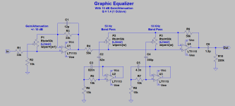
Yeah, I'm not sure what is going on with that input stage. But here is a revised LTspice schematic which adds a 10 dB gain/attenuation block which can be used in place of the original input stage. This block has non-inverting unity gain when its (linear) pot is centered, and provides 10 dB attenuation at the full counterclockwise position and 10 dB gain at the full clockwise position. Gain is established by R3 and R2 according to the formula Av=1+R3/R2. Of course, this input stage can be replaced with a simple buffer if desired.
LTspice is a popular simulator and most diyAudio members use it. It is free and can be downloaded at the following link.
https://www.analog.com/en/resources/design-tools-and-calculators/ltspice-simulator.html
LTspice is a popular simulator and most diyAudio members use it. It is free and can be downloaded at the following link.
https://www.analog.com/en/resources/design-tools-and-calculators/ltspice-simulator.html
Attachments

Thx, I meant, the gain of the bandpass...
Lets say first opamp is unity, the second opamp feedback Resistor and the first opamp output resistor should be the same (for equal boost and cut).
The value of the feedback resistor over something (I dont know) gives the gain of the bandpass.
If we increase the feedback resistor, the gain rises.
p.s. could it be that LT spice and proteus show different simulations and one of the softwares is wrong...
I cant replicate your simulation in LT spice, it will take a while to learn it
It is 15db now (on my simulation) and I can control it, but wanted to find a way not to increase the feedback too much (cause of noise)
In case I can cheat the linear pot to be seen as an 'S' pot with some resistor network, but I need more gain..
I am still at dismay - in general your circuit and my circuit are the same, just the simulation software is different..
And the kit seller warns in the description, that 'S' pot is needed for a linear response.
I didnt know it is that bad as my simulation shows (if it is correct, I doubt everything right now..)
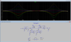
I can confirm that the circuit I provided does not require a special taper. Plain linear pots work just fine. The response is flat with the controls centered and the plot shows the range of boost and cut at the designed bandpass frequencies.
BTW, my circuit is an excerpt of a design I did for a commercial recording engineer. It does work and he is happy with it. 😉
BTW, my circuit is an excerpt of a design I did for a commercial recording engineer. It does work and he is happy with it. 😉
You and my simulation ran me into another doubt..
The simulation shows different gain at max settings for arbitrary chosen channels
You said the bandpass gain is 10 db.
I used this calculator, and it seems the particular elements set different center frequency and Q factor, but nothing about the gain..
https://www.muzique.com/lab/gyrator.htm
The simulation shows different gain at max settings for arbitrary chosen channels
You said the bandpass gain is 10 db.
I used this calculator, and it seems the particular elements set different center frequency and Q factor, but nothing about the gain..
https://www.muzique.com/lab/gyrator.htm
I can't speak to your simulation results but I can verify that my LTspice simulation results were verified through bench testing of an actual product. Simulation is a great tool but is no substitute for performance measurements.
What control range are you looking for? 10 dB is a fairly common value and is way more than enough in most applications.
What control range are you looking for? 10 dB is a fairly common value and is way more than enough in most applications.
Here is the frequency response of my test circuit with all of the controls centered. It provides overall unity gain across the audio band.

Actually, your circuit is not a gyrator like in the calculator and the kit I am working on, it is different topology.
I cannot make it run in Proteus, neither I can work with LT spice 🙁

Even If I go your way (I don't know if you are using a standard topology), I don't know how to calculate the Fc and Q factor for this filter.
Moreover, I have to design and make a new PCB, which alone would set me HUGE AMOUNTS of time back on the EQ module only 🙁 🙁
I cannot make it run in Proteus, neither I can work with LT spice 🙁
Even If I go your way (I don't know if you are using a standard topology), I don't know how to calculate the Fc and Q factor for this filter.
Moreover, I have to design and make a new PCB, which alone would set me HUGE AMOUNTS of time back on the EQ module only 🙁 🙁
Last edited:
I'm not suggesting that you "go my way" at all. Do what you want. I was simply offering some suggestions for where to look. But if you bought your equalizer as a kit then the seller should be willing to give you support, including answering questions about what kind of poteniometers are required for his product.
I really don't have the time or inclination to do a custom design for you. So maybe I need to exit this discussion because I don't think I can be of much more help. There are a lot of websites that discuss these kinds of designs, including formulas where appropriate. Google is your friend. 🙂
As for simulators, the vast majority of diyAudio members use, or are familiar with, LTspice. A smaller number use TINA or Microcap but Proteus users will be few and far between. Still, someone here might be willing to provide further help.
Good luck with this.
Thank you for the replies 😊
Here it is the S curve needed

Adding resistors (ends to wiper) would make an inverse S, and it would make the response even worse

And here it is a mfb bandpass (should use linear pots as far as I understood)
https://sound-au.com/project84.htm
Moreover it is a constant Q filter and contains calculators to set frequency and Q.
Making pcb to fit in my project would take time..
That's why I chose Proteus several years ago - I found it (at that moment) the best to learn, especially for pcb design.
Mby I've been wrong but it is still easier than learning a new software.
For hobby projects only 😀
Here it is the S curve needed
Adding resistors (ends to wiper) would make an inverse S, and it would make the response even worse
And here it is a mfb bandpass (should use linear pots as far as I understood)
https://sound-au.com/project84.htm
Moreover it is a constant Q filter and contains calculators to set frequency and Q.
Making pcb to fit in my project would take time..
That's why I chose Proteus several years ago - I found it (at that moment) the best to learn, especially for pcb design.
Mby I've been wrong but it is still easier than learning a new software.
For hobby projects only 😀
Last edited:
too many opamps!
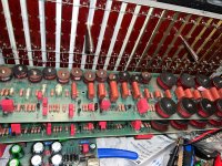
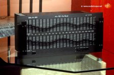
SAE MK 2700 - 20 inductor / capacitors bands and 8 transistors class A per channel with resistor and capacitor update.
5U - 9 inches tall - discontinued because it was too big and too expensive to build - circa 1977
SAE MK 2700 - 20 inductor / capacitors bands and 8 transistors class A per channel with resistor and capacitor update.
5U - 9 inches tall - discontinued because it was too big and too expensive to build - circa 1977
Attachments
Last edited:
WHITE (brand) equalizer with rotary pots. ( bargain price )
https://www.avgear.com/product/whit...4b81lGm2YpU75bkgDlAUqTlTnpmoDm_qS2o3Nb6pMgYfw
More about White Instruments.
http://www.whiteinstruments.com/
https://www.avgear.com/product/whit...4b81lGm2YpU75bkgDlAUqTlTnpmoDm_qS2o3Nb6pMgYfw
More about White Instruments.
http://www.whiteinstruments.com/
Last edited:
This is the unbeatable form factor, a pcb with 3x4 opamps:
Post in thread 'graphic EQ with linear pots' https://www.diyaudio.com/community/threads/graphic-eq-with-linear-pots.420802/post-7863171
That's why I chose the kit in the first place...
Rod Eliot's mfb has one discrete element per band more, but I have to design a pcb inspired by the layout of the kit above.
The point is I have to incorporate the EQ in an old project of mine

Totally retro and obsolete by design, but I have to finish that 😄
Nowadays they have triple the power and serious parametric EQ in a fraction of the weight and size (class D, smps).
But this one is not going to be a road professional equipment.
Will stay in a hobby rehearsal place.
- Home
- Source & Line
- Analog Line Level
- graphic EQ with linear pots