Hello folks,
I recently completed soldering a Gardo PH-1 clone, which I've bought via Aliexpress https://www.aliexpress.com/item/1005003264368348.html, but it's available form several resellers on eBay as well. But that's not the point.
I choose this one, as the same seller offers a Accuphase C-3850 kit (either assembled or as a solder kit) which has an identical circuitry in the power supply stage,
both use LM7815 / LM7915 voltage regulators and a KBP307 Single Bridge Rectifier for the AC 15-0-15 input and both came with an JRC 5532D within the kit.
As the power stage is more or less redundant, I'm looking to eventually replace the circuitry to a dedicated board. As there are several topics about the Accuphase C-3850 clone already, I won't go into details within this topic about the power stage.
But I'ld like to hear recommendations about the Gardo PH-1 implementation and to which effect the circuit could be improved to reduce potential noise.
For myself, I'm not really into electrical engineering. But I can hold a soldering iron without burning myself, most of the time 😉 I don't have advanced measuring equipment in terms of audio analysis or function generators. Only my eyes, ears and a multimeter. Thus, I definitely a beginner who is willing to leave his zone of comfort to improve upon the given implementation of this phono stage.
For the moment, the only alterations to the circuit was that I've replaced the JRC 5532 D Op-Amp with a LME49720NA, which has reduced the noise level quite a bit (just based on signal output / full volume amplification)
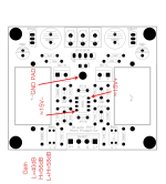
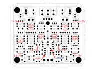
Here is the schematic the seller is sharing without the specific values of the components:

And the layout of the PCB

And finally, the BOM, more or less.

Sadly, the whole kit came without further instructions, thus not everything is totally clear. But soldering went without issue and the phone stage worked directly.
Otherwise, I'm still in the process to finish the housing for this phono stage as well as the clone of the Accuphase C-3850, which will live in the same enclosure and sharing the same transformer (please cry now if that is a bad idea overall).
And one simple question which I've got - as the pcb design features a common ground pad, should I solder a ground wire to it and connect it to the terminal that is shared with the ground lead from the turntable ? The Accuphase C-3850 also has a common ground pad and I'm asking myself if both or only the phono stage should be wired to that ground terminal.
I recently completed soldering a Gardo PH-1 clone, which I've bought via Aliexpress https://www.aliexpress.com/item/1005003264368348.html, but it's available form several resellers on eBay as well. But that's not the point.
I choose this one, as the same seller offers a Accuphase C-3850 kit (either assembled or as a solder kit) which has an identical circuitry in the power supply stage,
both use LM7815 / LM7915 voltage regulators and a KBP307 Single Bridge Rectifier for the AC 15-0-15 input and both came with an JRC 5532D within the kit.
As the power stage is more or less redundant, I'm looking to eventually replace the circuitry to a dedicated board. As there are several topics about the Accuphase C-3850 clone already, I won't go into details within this topic about the power stage.
But I'ld like to hear recommendations about the Gardo PH-1 implementation and to which effect the circuit could be improved to reduce potential noise.
For myself, I'm not really into electrical engineering. But I can hold a soldering iron without burning myself, most of the time 😉 I don't have advanced measuring equipment in terms of audio analysis or function generators. Only my eyes, ears and a multimeter. Thus, I definitely a beginner who is willing to leave his zone of comfort to improve upon the given implementation of this phono stage.
For the moment, the only alterations to the circuit was that I've replaced the JRC 5532 D Op-Amp with a LME49720NA, which has reduced the noise level quite a bit (just based on signal output / full volume amplification)
Here is the schematic the seller is sharing without the specific values of the components:
And the layout of the PCB
And finally, the BOM, more or less.
Sadly, the whole kit came without further instructions, thus not everything is totally clear. But soldering went without issue and the phone stage worked directly.
Otherwise, I'm still in the process to finish the housing for this phono stage as well as the clone of the Accuphase C-3850, which will live in the same enclosure and sharing the same transformer (please cry now if that is a bad idea overall).
And one simple question which I've got - as the pcb design features a common ground pad, should I solder a ground wire to it and connect it to the terminal that is shared with the ground lead from the turntable ? The Accuphase C-3850 also has a common ground pad and I'm asking myself if both or only the phono stage should be wired to that ground terminal.
As I only realize it now, I've messed up with posting this thread to the analog line level instead of analog source section of the forum. If a moderator would be so kind to move the thread into the correct subsection, I'ld appreciate it ! Sorry for the inconvenience.
I'm just wondering why you decided to go with a clone of this particular phono preamplifier. Grado PH-1 is not really better (or worse) than any number of single-stage opamp based phono stages out there. There is only so much you can do to improve it.
When it comes to the ground wire from the turntable, in my opinion it should be connected to the 0V rail on the PSU.
When it comes to the ground wire from the turntable, in my opinion it should be connected to the 0V rail on the PSU.
Last edited:

I just wanted one in kit form, which I could solder myself without the hassle of sourcing all required parts separately. A complete build from scratch is currently out of scope, due to basic knowledge on my side. I've bought a linear power supply stage from that seller before and the PCBs were quite nice and I didn't had any issues with it. It's quiet affordable and I was going to purchase the Accuphase C-3850 clone from that seller anyway.
That being said, I don't have the intention to create / design a high-end audiophile phone stage which outperforms commercial available products. That would be a long term motivation, indeed. But totally unrealistic at the current stage. It's just a start into a new topic for me. And it's uncertain how deep I'll dive into it.
That being said, I don't have the intention to create / design a high-end audiophile phone stage which outperforms commercial available products. That would be a long term motivation, indeed. But totally unrealistic at the current stage. It's just a start into a new topic for me. And it's uncertain how deep I'll dive into it.
My only concern about this circuit is that the cartridge is DC coupled to the opamp input. With BJT opamps the base current of the input stage will flow through the cartridge. While it would not cause any permanent damage to the cartridge, it could theoretically interfere with its magnetic circuit (and will definitely slowly magnetise the core of the cartridge over time). This is especially true for opamps like 553x that are known to run their input stage at relatively high currents.
Personally I would use something like the OPA1642 in this circuit. It is a very low noise JFET-input opamp, and it is also optimised for low distortion with high impedance sources. The only issue is that it is an SMD part, but there are many sellers that offer SMD opamps premounted to DIP adapters.
Personally I would use something like the OPA1642 in this circuit. It is a very low noise JFET-input opamp, and it is also optimised for low distortion with high impedance sources. The only issue is that it is an SMD part, but there are many sellers that offer SMD opamps premounted to DIP adapters.
Last edited:
Thanks for that insight ! As that one isn't really that expensive, even with a DIP8 socket adapter, I guess I'll add it to my next purchase.
At the moment the enclosure for this phono stage as well as the accuphase c-8050 clone is almost completed. But I'm having a interference / noise when I feed the phono stage into the preamp circuit. As it's more or less just a passive input selector for the source selection ( JST-XH connector & rotary selector) and the volume control of the preamp is a 50k log potentiometer at the input side of the preamp, that obviously doesn't work as I thought. The phono signal even begins to oscillate a little when I turn the volume up too high when amplfied.
Guess it's really a bad idea to feed both circuit boards from the same R-Core transformer which only had one 15-0-15 secondary winding.
Individually they work fine, without issue. But not in combination.
Ah, I see now, the phono preamplifier has its own onboard power supply. Does the C-3850 clone also have its own onboard PSU? You should definitely connect GND from both boards together and to the chassis, and the turntable ground wire should also connect to the same point.
It does not only have a onboard PSU as well, it's circuitry on board is actually identical, the very same components (voltage regulators as well as the same single bridge rectifier). The only difference is that the Accuphase clone uses 100uF 35V electrolytics from Rubycon behind the voltage regulators instead of the 100uF 50V electrolytics from Nippon Chemi-Con in the circuit of the Gardo PH-1 clone. Which shouldn't really make any difference I think.
I connected the secondary winding of the 15-0-15 transformer to both pcbs via the screw terminals, taking the polarity into account, and soldered on a ground wire to the given ground pads and connected them to the binding post for the ground of the turntable, but not to each other directly. I also had the ground wire of the primary winding of the transformer connected to the same binding post / ground to the chassis.
Currently I'm doing the last step of metalworking to cut out the opening for the mains socket and will investigate the issue further once I'm done with that task.
Attachments
In short, I redid some of my wiring (soldered JST-XH terminals onto both pcbs). I must have done a poor crimping job beforehand, as there has been bad connections. I'm using shielded cables, Lapp Kabel Unitronic LiYCY 3x 0.14mm for the audio signals. Besides poor crimp connections, I may have cut into the individual leads, when I was stripping the sheating and shielding. I really should invest into proper crimping pliers for this task, such as the Engineer PA-9, as the pliers which I've got are to clunky and the crimping result is a hit or miss. Could have been totally avoided by wiring in unshielded wire leads instead of the shielded cables instead.
I also realized that the layout of the PSUs on the PCBs is mirrored in the vertical axis. Therefore my connections from the secondary winding of the transformer to the PCBs has been incorrect. Both that shouldn't really make a difference?
Anyway, based on your suggestion, I ultimatively desoldered the voltage regulators of the phono stage, soldered on jumper wires from the voltage regulators leads of the preamp, feeding the 100uF capacitors off the phono stage. And that reduced the inteferences / noise signifianctly.
Nevertheless, I need to check the phono stage once again for bad solder joints. As the left channel dosn't work when I set the dip switches to low and high to achieve +58dB gain. But low (40dB) and high (56dB) gain are working, for now I can live with the high setting as the additional 2dB aren't that significant. Haven't removed the other components of the power supply on the phono stage yet.
Thanks alot for your input up so far ! I'll definitely try to get my hands on OPA1642s to compare them to the other OpAmps which I've got already.
Good job! Yes, poor connections can cause many problems. I actually prefer to solder wires on all my builds for this very reason.
For now I'm just listening to it with my regular setup and must say... it's not perfect. There is still a constant hissing sound in the audio signal which is bothering me. The build-in phono stages of my other amplifiers do a better job (Marantz PM-35 Mk 2 & Marantz PM4200). For me, this project is more or less intended as a input source for my Fosi Audio v3 stereo amplifier which uses an SMSL SU-1 DAC as an input for digital sources, I'm quite happy with this setup so far. The Accuphase C-3850 clone on it's own seems to work without issues up so far..
Listened to it at 56dB gain setting. Did some comparisons, just to check. With or without the Accuphase as an preamp. With or without the 50k log potentiometer. With or without passive source selector switch. All with the LME49720NA as Op-Amp instead of the JRC 5532 D the kit shipped with.
I've got the impression that the hissing sound is at the very same level when the phono stage is set to 40dB. And therefore much more audioble when I increase the volume to listening levels at 40dB. It's present, even when there is no playback signal from the turntable or the turntable switched off.
Will investigate this further at a later point, But not as of today. At the moment I'm not in the mood and prefer it to contemplate other things. Such as which knobs to use for the front panel. And if I'm going to strip the nickel plating of the fasteners of the on-off switches and to cold-blue them instead. In short, I'm much more comfortable doing the metalworking as I'm more expierenced with this kind of work. Instead of troubleshooting electronic circuits without access to proper testing equipment and almost no clue
Edit:
Btw.: I've got a Metz Mecasound TX-4963 record player which has been restored and upgraded by a expert here in town. Proper RCA cables instead of DIN cables and a Audio Technica AT 91 R cartridge, noting fancy essentially.
Last edited:
Well, 56dB (~630x) is a LOT of gain for a single opamp gain stage, and especially for something like LME49720 (which is the same as LME4562). Is your cartridge MM or MC?
MM cartridge. At least Its a ATN91R stylus, thus I assume it the AT91R cartridge as well. Definitely MM.
You definitely don't need 56dB of gain for an MM cartridge. Since the basic model of a phono cartridge is an inductor, its impedance is not linear and actually rises with frequency, which means that the opamp's current noise is directly converted into annoying hiss, which in turn is amplified by the phono stage...
MC cartridges are much less susceptible to this because their inductance is several orders of magnitude lower than the inductance of a typical MM cartridge.
MC cartridges are much less susceptible to this because their inductance is several orders of magnitude lower than the inductance of a typical MM cartridge.
Last edited:
Well, I have to admit that I never really considered how much gain would be suitable. The data sheets from audio technica for the entry level cartridges don't provide recommendations in terms of gain settings, only 47 kOhms for the load impedance and 100-200pf for the load capacitance are recommended.
All I can tell that the old Marantz PM-35 Mk.2 integrated stereo amplifier which I've used before has a phono stage that has been totally fine for me. But I can't tell how much gain it uses for MM cartridges, only have these technical specifications of that amplifier.
Phono (MM):
Frequency Response (IEC RIAA): +/- 0,5dB
Signal-to-Noise Ratio (IEC A weighted): 86dB
Input Impedance: 47 k ohms
Input Capacitance: 200pF
Input Sensitivity: 2,5mV
Equivalent Input Noise: 0,25µV
Phono (MC):
Input Sensitivity: 250µV
Input Impedance: 100 ohms
Also, I don't have the means to check if the gain levels for this Gardo PH-1 clone which are specified for the dip switch settings are actually precise.
I'll definitely check the resistors on the pcb for an eventual mistake from my side. And, as I said already. There is already an fault with the left channel when I enable both, the low and high gain. It's actually a bit cumbersome that the seller didn't delivered a complete schematic with all the traces and component values. Just the pcb, and the components. No documentation other than the images which I've posted at the initial post. The blank pcb has been clearly labeled where each component has to go.
Anyway, what would be your suggestion ? Would 40 dB of gain even too much for the MM cartridge I'm using ?
Your Marantz has approximately 35dB of gain at 1kHz (phono stage only, not counting the line stage and the main amplifier).
It also has JFETs at the input which means that it should be much quieter than the bipolar LME49720.
40dB of gain should be fine for the Audio-Technica cartridge.
It also has JFETs at the input which means that it should be much quieter than the bipolar LME49720.
40dB of gain should be fine for the Audio-Technica cartridge.
Last edited:
- Home
- Source & Line
- Analogue Source
- Grado PH-1 clone - phono stage DIY kit