The good news is that I got one channel almost 'together' and it sounds pretty good even though it doesn't look too hot yet.
I am having two issues that I assume are related. 1st issue is that the bias drifts on the Q3 side. The thermistor changes resistance when I put my hot finger on it. I removed R15 and R3 and measured their values - 2.2k. Q4's bias tracks very well from cold to hot. Q3 will start out cold at over .7 volts across R11 and come into range pretty quickly within a minute - there is an offset at the output during this imbalance. I also verified the resistance of both R11 and R12 - they are the same, although they measure .6 ohm instead of .47. On both sides the thermistors are glued to the transistor body.
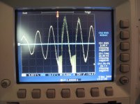
The second issue is that when I turn up the volume - once the voltage across R3 and R4 just comes off idle (coming out of class A?) I get bad distortion that sounds like the scope shot below looks. I don't know if that is the current limiting coming into play? it seems kind of rough - it looks like what I would see from a broken amplifier. This is with an 8 ohm speaker connected.
I guess I could pull Q5 and Q6 out and see if the distortion goes away but I figured I would check for input here first since I figure both problems are probably related.
I am using 2Sk170/2SJ74's and FQA19N20c/FQA12P20 and PDaniel boards.
Any thoughts? Thanks!
I am having two issues that I assume are related. 1st issue is that the bias drifts on the Q3 side. The thermistor changes resistance when I put my hot finger on it. I removed R15 and R3 and measured their values - 2.2k. Q4's bias tracks very well from cold to hot. Q3 will start out cold at over .7 volts across R11 and come into range pretty quickly within a minute - there is an offset at the output during this imbalance. I also verified the resistance of both R11 and R12 - they are the same, although they measure .6 ohm instead of .47. On both sides the thermistors are glued to the transistor body.
The second issue is that when I turn up the volume - once the voltage across R3 and R4 just comes off idle (coming out of class A?) I get bad distortion that sounds like the scope shot below looks. I don't know if that is the current limiting coming into play? it seems kind of rough - it looks like what I would see from a broken amplifier. This is with an 8 ohm speaker connected.
I guess I could pull Q5 and Q6 out and see if the distortion goes away but I figured I would check for input here first since I figure both problems are probably related.
I am using 2Sk170/2SJ74's and FQA19N20c/FQA12P20 and PDaniel boards.
Any thoughts? Thanks!
Attachments
Last edited:
The scope shot looks like it's bursting into high frequency oscillation to me..I'm no pro on the F5 though,so we'll see what the others think. 🙂
Hmmm. . . I seem to have lost the ability to edit my posts. Too many edits in one day maybe?
I will try some caps in the morning and see if I can tame the beast.
I will try some caps in the morning and see if I can tame the beast.
1.6mhz is the frequency it bursts at.
Putting a cap across R10 seems to quell it. Now to figure out the ideal size.
Putting a cap across R10 seems to quell it. Now to figure out the ideal size.
Ok, that's working. Any ideas about the cold bias on Q3? If not I will live with it until I build the next channel and see if it behaves the same way.
Thanks!
Thanks!
It seems to me
If I say "I think I see capacitors on that board"
You are supposed to respond with an explanation as to
what those capacitors are / or not are.
If I say "I think I see capacitors on that board"
You are supposed to respond with an explanation as to
what those capacitors are / or not are.
Prediction !!!
Nelson Pass:
what those capacitors are / or not are.
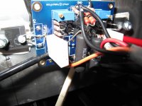
From the description (Fairchild devices) and a few other clues (vertical resistor mounting, R5..R8 replaced with a pair of 50 ohm Dale 6.5W units, etc) -- I'm going to predict that you're seeing a tech-diy parts kit.
Which means the big white items at R11 and R12 are Ohmite TWW5 resistors. http://www.ohmite.com/cgi-bin/showpage.cgi?product=tww_twm_series
Rick
Nelson Pass:
what those capacitors are / or not are.
From the description (Fairchild devices) and a few other clues (vertical resistor mounting, R5..R8 replaced with a pair of 50 ohm Dale 6.5W units, etc) -- I'm going to predict that you're seeing a tech-diy parts kit.
Which means the big white items at R11 and R12 are Ohmite TWW5 resistors. http://www.ohmite.com/cgi-bin/showpage.cgi?product=tww_twm_series
Rick
Oh, those - they are MPC71 .47 ohm resistors.
Correct - it is mostly Tech-DIY parts
I thought that "I think I see capacitors on that channel board." was a kind of cryptic clue pointing towards adding some capacitors to that channel.
Correct - it is mostly Tech-DIY parts
I thought that "I think I see capacitors on that channel board." was a kind of cryptic clue pointing towards adding some capacitors to that channel.
Last edited:
No, I was pointing toward the possibility that you added
film caps from supply to ground on the circuit board. That
typically will push you over the edge on stability in a manner
that looks like your scope trace.
😎
film caps from supply to ground on the circuit board. That
typically will push you over the edge on stability in a manner
that looks like your scope trace.
😎
If I am seeing it right, you made the same mistake that I did. One end of the output resistor is in the wrong hole.
The two holes that you have the resistor in are actually connected together. The proper hole for the other end of the resistor is just above the box (in the board orientation in your photo).
The two holes that you have the resistor in are actually connected together. The proper hole for the other end of the resistor is just above the box (in the board orientation in your photo).
Last edited:
Checked it with my DMM just now. Both holes are indeed connected together. Well spotted preiter! See the picture on how to use the hole inside the box correctly: http://www.diyaudio.com/forums/showpost.php?p=1771389&postcount=1
Last edited:
The drifting bias is the giveaway. Same symptom I had. By not hooking that resistor up properly you had disconnected the feedback path.
Holy C!!P - I think you are right! Unfortunately I won't see the amp until I get back to Florida on Friday. I saw those other two holes and thought they were just jumpers to get the trace from one side of the board to the other. I feel like an idiot now, looking at the picture of the board I can clearly see that all the legs of my resistors are connected to the same trace.
I guess now I know what an amp with no feedback sounds like.
I guess now I know what an amp with no feedback sounds like.
Yeah, I did that too with the PD boards. Took a fair bit of head scratching to sort it out. My clue was that I had it in both channels so I knew it was something systematic I did.
I did look at your pics for that, but couldn't see it.
Fran
I did look at your pics for that, but couldn't see it.
Fran
At least you didn't put capacitors in the circuit.
😎
Good Point!
- Status
- Not open for further replies.
- Home
- Amplifiers
- Pass Labs
- Good Gnews and Bad Gnews w/ my F5 - help?