I have a GTA SE-40 that I recently fired up. I noticed that the power LED was not lit... The next thing I noticed was that the filaments were not glowing for the pair of 6SN7. The odd thing was all six of the 5881 filaments were lit. I wonder if the input pair and the output sextet are on separate supplies for some reason? I haven't been able to find a schematic.
Check continuity of the filament wiring with a DVM, there may be a bad solder joint or open trace.
That's what I was thinking. It seemed the socket for the 6SN7 filament measured open circuit... I tried tying the filament pins of one 5881 [2-7] to the filament pins of one 6SN7 [7-8] as a test. No go.
That's what I was thinking. It seemed the socket for the 6SN7 filament measured open circuit... I tried tying the filament pins of one 5881 [2-7] to the filament pins of one 6SN7 [7-8] as a test. No go.
Unplug and discharge the amp, and remove all the tubes. Use an ohm meter between the 6SN7 and the 5881. You should get continuity between a pin (7 or 8) of the 6SN7 to a pin (2 or 7) of the 5881. If not, there may be a DC filament supply for the 6SN7 that is out.
Last edited:
I haven't been able to find a schematic.
There have been a few posts on Audiokarma over the years for this amp, but never with a schematic.
jeff
Schematic yes, but not with the power supply.
Golden Tube Audio SE-40 - Manual - Stereo Power Amplifier - HiFi Engine
Golden Tube Audio SE-40 - Manual - Stereo Power Amplifier - HiFi Engine
The GTA-40 has an AC supply for V2,3,4, another AC supply for V5,7,8, and a DC supply for V1,2.
Then the DC supply is bad, maybe an open resistor or diode.
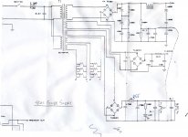
I have both regular and special editions of the SE-40 including one Rev4 version. In the attached schematic R55 is used to drop the voltage after rectification. It gets hot enough to burn you.
The Rev3 versions that I have were designed for 110-115 volt line level. The filament voltage on the SN7s is above 7 volts. I replaced that resistor with a 10 watt one of slightly higher resistance to reduce the filament voltage to something closer to 6.3 volts.
The Rev4 vesion (their last) was designed for line level closer to 120 volts and all the filament voltages are within tolerances.
If the LED is not lit I would check R55 and the resistor in series with the LED.
Steve
Attachments
Thanks for the power supply schematic Steve. It looks like R55 is one Ohm. Did you consider bypassing the rectifiers and running the filaments for V1, V2 off 6.3VAC?
...j
...j
At the time I only owned one se-40 so I changed the resistor to an appropriate value. Later I bought 2 special edition versions and another regular edition. The resistor values were different on 3 of the amplifiers because the actual line level requirements of the PTs were different.
I think the best solution would be to use an LM317 after the rectifiers and set it for the required voltage. The heat dissipation is so small that you may not require a heatsink. And there is sufficient room inside the chassis for this improvement.
See the link below for an LM317 heat sink calculator
Constant Voltage Regulator
These changes do not affect the power tube filament voltages but within the tubes published specs on my amps. The voltages on the 6SN7 filaments are higher than the power tubes because of the solid state rectification and hence outside the published tubes specs.
Steve
It is my understanding that the LED needs DC to operate because with AC the reverse voltage half cycle may exceed its reverse voltage limit and cause thermal breakdown.
Leaving the rectifier in for the LED and bypassing it for the tubes is an option.
I didn't do it because it is a more significant modification on the PCB than changing a resistor. And if I was going to do that then I would rather do the LM317 mod.
Steve
Leaving the rectifier in for the LED and bypassing it for the tubes is an option.
I didn't do it because it is a more significant modification on the PCB than changing a resistor. And if I was going to do that then I would rather do the LM317 mod.
Steve
You can add a diode in anti-parallel with the LED, and feed it AC through the dropping resistor.
Rayma
Thanks, I learned something after doing a web search to understand your suggestion.
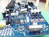
In the image the green power indicator LED is on the right. The dropping resistor is the 5 watt cement resistor on the left. And the bridge rectifier is in the foreground in front of the resistor.
It would be simple to replace the resistor with an LM317 and a couple resistors on a small proto board and grab ground from readily accessible locations on the system board.
This is why I would do the LM317 mod as opposed to anything else.
Steve
Thanks, I learned something after doing a web search to understand your suggestion.
In the image the green power indicator LED is on the right. The dropping resistor is the 5 watt cement resistor on the left. And the bridge rectifier is in the foreground in front of the resistor.
It would be simple to replace the resistor with an LM317 and a couple resistors on a small proto board and grab ground from readily accessible locations on the system board.
This is why I would do the LM317 mod as opposed to anything else.
Steve
Attachments
Remember the LM317 needs 3V drop minimum, including the lowest point of the input voltage ripple.
Rayma,
Again an important point. I did not think about that.
It only works if your line voltage is very high and you have one of the lower line voltage versions. Now I don't I don't think the LM317 is a suitable solution.
On the one that I modded for my son ( by changing the resistor) the AC before the bridge was 7 volts because his line voltage was much greater than 120 volts. I think I used a 2 ohm resistor on his.
Is there a suitable regulator with a lower dropout voltage?
Steve
http://www.ti.com/lit/ds/symlink/lm2941.pdf
Instead, you could use a voltage doubler with a suitable value of series resistor, and a final filter capacitor.
Instead, you could use a voltage doubler with a suitable value of series resistor, and a final filter capacitor.
Last edited:
So I converted the SE-40's 6SN7 to AC filament supply... and it works fine. I was surprised to find that the transformer tap was 8.6VAC (no load) not 6.3VAC or thereabouts. I had a 10W, 2 Ohm resistor that I put in series with pins 7 and 8 of the 6SN7 which yielded 5.8VAC with the tubes in place. The 2 Ohm runs fairly warm--about 170F.
The PCB seems okay. The pair of 4700uF caps on either side of R55 measured okay, they are out of the circuit. R55 measured okay at about 1.7 Ohms. To my thinking that leaves the bridge rectifier as the prime suspect. I don't think is undersized, and I don't recall having one fail previously.
I intend to debug the DC filament supply since it is not regulated.
- Status
- Not open for further replies.
- Home
- Amplifiers
- Tubes / Valves
- Golden Tube Audio SE-40 filament supplies