Hello all,
A bit of a noobie here (2nd year physics and electronics, bla, bla ,bla) mostly doing audio. I took apart the power module form the Pre-73 that uses a 24VAC wall adapter to run. After careful examination (it wasn't that complex actually) I came up with this schemo. Please let me know if it makes sense, did I miss anything? Looks ok to me but...Can I also replace the choke (circled) for a RC filter instead? This would supply +48V and +24 from the 24VAC. The 7824 hooks up to a 33v Zener. Values are not in the Eagle schem yet cause I wanted to make sure it was corect .
Thanks
L
Attachments
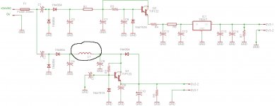
I took apart the power module form the Pre-73 that uses a 24VAC wall adapter to run. After careful examination (it wasn't that complex actually)
I came up with this schemo. Please let me know if it makes sense, did I miss anything?
Capacitors C1 and C2 are in shunt, and are not series elements. The DC current could not flow through them if they were in series.
Last edited:
- Status
- Not open for further replies.