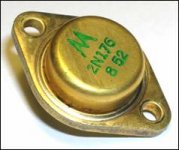
I was amazed about the circuit topology in vintage receivers for car audio. Especially Motorola used this topoloy in their hybrid (i. e. tube & solid state) car receivers and therefore Motorola prefer gold plated TO-3 (2N176 and 2N178). Such vintage car radios in Germany are very hard to find. The German brands Blaupunkt and Becker uses at the same aera (1958-1963) push pull concepts (mostly equipped with Siemens TF78 or TF80), but also not OTL.
Are there any experience about sound quality of the Motorola topology?
Perhaps it could be excellent with high quality power supplies and after replace the output and driving transformers through high quality versions e. g. from Lundahl.
Also very interesting to know it would be, if there are from the same aera, we say between 1958 - 1964 also single ended solid state Motorola/Bendix amplifier components for domestic/hifi hifi/audio
Thank you for your comments and informations.
More pics, schemas and informations about this vintage products you will find by post #24, #25 and #26 about
http://www.diyaudio.com/forums/parts/167680-vintage-transistors-3.html#post2203311
the third jpg file from post #24 shows the schema of Motorola's single ended output power stage with the 2N176.
Attachments
Last edited:
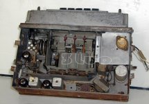
Bendix Single Ended Audio Power Stage
Bendix uses for the power amp stage in their car receivers even by the first "full transistorized" versions still no push-pull Class_B - go to post #35 about
http://www.diyaudio.com/forums/parts/167680-vintage-transistors-4.html#post2204039
You will find in the attached schematic an aditional interesting thing: OTL, but parallel to the speaker output (and instead a boucherot/zobel network) an inductor (transformer outline). The same seems to be by the car radio from the third attached picture
What could be the reason therefore?
Attachments


Last edited:
no informations?
Ok, well that choke shunts the power transistor collector current to ground to complete the circuit. You don't want a lot of dc current through a speaker coil since that will move the cone up or down such that audio peaks will bottom out the cone. The choke is likely around 100mh in inductance. The text is fuzzy, but it looks like the choke has 1.065 ohms DC resistance. The speaker says (again fuzzy) 6 ohms. I know that speakers like this often have the coil DC resistance about the same as the nominal impedance. So if the collector current was 1/2 ampere ( a guess for a class A 12v audio power amplifier), the speaker might only see 1/6th of that, or about 80 ma.
A better approach that minimizes speaker current even more, and offers a better impedance match is to use the choke with a tap as shown below:
Looking for vintage car radio audio output transformer
I believe this circuit is from a 1963 Rambler car radio.
Anybody have any of these tapped chokes from the 1960's car radio's? I use them as ham radio modulation transformers, for transmitters like the Small Wonders Laboratories Retro-75 AM Transceiver.
Jim
WD5JKO
thank you for this explantation. By reading this I note, that there is no serial high pass capacitor in use for DC blocking - that I have overlooked completly. Without such capacitor and loudspeakers, which can tolerate a certain amount of DC components, the aim of the coil I understand.
- Status
- Not open for further replies.