Hi
Not sure to understand (sorry my english in not very good), is it 15W anode dissipation per tetrode - 30W total - or 7.5W each ?
http://www.ok1rr.com/tubes/GMI6.pdf
http://www.ok1rr.com/tubes/GMI6-1.pdf
Thanks 🙂
Not sure to understand (sorry my english in not very good), is it 15W anode dissipation per tetrode - 30W total - or 7.5W each ?
http://www.ok1rr.com/tubes/GMI6.pdf
http://www.ok1rr.com/tubes/GMI6-1.pdf
Thanks 🙂
Best I can tell that is the combined dissipation of both plates, so it is 15W total for both, and 7.5W per plate. Others may have a different interpretation..
Good luck!
Good luck!
Yes, it is 15W total dissipation for 2 anodes.
Similar cases are 832A/GU-32 (ГУ-32); QQV06-40A/GU-19-1 (ГУ-19-1)...
Similar cases are 832A/GU-32 (ГУ-32); QQV06-40A/GU-19-1 (ГУ-19-1)...
When looking at the size of GMI-6 I would say that 15 W / tube ( 7,5 W/ anode) is quite gentle dissipation for such tube.
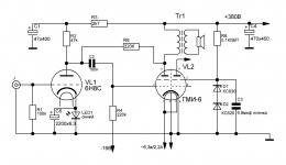
Anyhow, I built a PP-prototype with GMI-6-1 a couple years ago.
It is easy to get 25...28 W with this tube.
Below is the schematic I used:
Technical details:
Transformer Edcor CXPP50-MS-6.6k (6k6 to 8), Ub = 400 V, Ug2 = 250 V, Ia(q) = 35 mA,
Pout(max) = 28 W, THD = 1,1 % (no GNBF), Zout = 50 ohms (no GNFB)
Anyhow, I built a PP-prototype with GMI-6-1 a couple years ago.
It is easy to get 25...28 W with this tube.
Below is the schematic I used:
An externally hosted image should be here but it was not working when we last tested it.
Technical details:
Transformer Edcor CXPP50-MS-6.6k (6k6 to 8), Ub = 400 V, Ug2 = 250 V, Ia(q) = 35 mA,
Pout(max) = 28 W, THD = 1,1 % (no GNBF), Zout = 50 ohms (no GNFB)
Thanks all for the input.
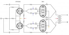
I'd like to try something like this, do you see errors on the schematic ? because of common shared cathode, 1 ohm resistor on each plate and all grids #1 individually biased, to avoid red plating.
I don't need a lot of power as speakers are quite sensitive (97dB), 10W most class A preferably - should be plentiful.
What I already have:
- input phase splitter transformer
- 4200/8 PP OPT
- tubes..
These little GMI-6 are really cool looking 🙂
Attachments

...I don't need a lot of power as speakers are quite sensitive (97dB), 10W most class A preferably - should be plentiful...
Then why do want to have two GMI-6 tubes when you could get 25 W with just one ??
- I've never heard a PPP
- 4200/8 OPT seems to be better suited for a PPP with these tubes (?)
- 8-10W power most class A without stressing too much the tubes
- 4200/8 OPT seems to be better suited for a PPP with these tubes (?)
- 8-10W power most class A without stressing too much the tubes
4200/8 OPT is just fine if you only need 10 W.
Why class A ?
Class A does not automatically mean "better sound" or better linearity.
With class AB1 and given voltages/current the distortion is smaller (with GMI-1).
In general class A is stressing tubes more than AB1 because of higher quiescent power.
Also the efficiency is worse in class A.
Why class A ?
Class A does not automatically mean "better sound" or better linearity.
With class AB1 and given voltages/current the distortion is smaller (with GMI-1).
In general class A is stressing tubes more than AB1 because of higher quiescent power.
Also the efficiency is worse in class A.
Last edited:
Why class A ? I tought it is better, but it seems to be a little bit more complicated..
Anyway, I also have less sensitive speakers, why not try AB.
Other option, input pentode LTP, is it going to work like this ? GMI-6 / GU-29 seems to be easy to drive (30-40Vpp).
Suggestions welcome.
Thanks.
Anyway, I also have less sensitive speakers, why not try AB.
Other option, input pentode LTP, is it going to work like this ? GMI-6 / GU-29 seems to be easy to drive (30-40Vpp).
Suggestions welcome.
Thanks.
Attachments
Last edited:
hello ,
le montage serait mieux en PP classe AB , en classe A , peut etre pas !
The assembly would be better in classy PP AB, in class A, can etre not!
Jean Michel ...JMD91 😉
le montage serait mieux en PP classe AB , en classe A , peut etre pas !
The assembly would be better in classy PP AB, in class A, can etre not!
Jean Michel ...JMD91 😉
tube gmi6
hola ,se puede usar este tubo Gmi-6 ,con una carga de 8k ?? push-pull ??
o 6.6k ?? para 30 watts ?? gracias best regards
hola ,se puede usar este tubo Gmi-6 ,con una carga de 8k ?? push-pull ??
o 6.6k ?? para 30 watts ?? gracias best regards
emk2,
Be sure to tell others that what makes your schematics work is that you use individual fixed negative bias, or individual fixed adjustable negative bias at each Blue Arrow.
Thanks!
Be sure to tell others that what makes your schematics work is that you use individual fixed negative bias, or individual fixed adjustable negative bias at each Blue Arrow.
Thanks!
artosalo,
The way you got that single dual beam power tube to put out 25 to 28 Watts, is the fact that it is push pull. Nice!
That illustrates a very good application of that tube.
But the original poster wants single ended dual channels from a single dual beam power tube. Lots different.
The same single dual beam power tube when used as two single ended amplifier channels will not put out 25W/2 = 12.5W per channel, and not 25 Watts total, unless you like red-plating that tube, and listening to it for a few minutes until the glass melts, or the screen shorts to another element.
Last edited:
emk2,
I did not even notice the Schade negative feedback in your schematics until now.
That could be pretty sweet.
I seem to remember Gary Pimm doing something like that over 2 decades ago with old type 47 tubes.
One thing to think about the schematic that has the input splitter transformer.
The most important part in that circuit is not even the output transformer (which is usually the case).
The most important part in that circuit is the Input splitter transformer.
The quality and performance of that part is paramount.
Then, after that, the output transformer quality and performance comes next.
I like the idea of using an LTP phase splitter.
I build phase splitter/drivers that use a current sink in the connected cathodes of that stage. That is just my preference.
Using a resistor there requires the resistor to be returned to a very large voltage.
Even with that, the balance is not perfect. Instead a current sink with an order of magnitude higher impedance (required to be across the audio band), will have a more perfect balance of the two outputs from the phase splitter.
Interesting LNFB loop, agreeing with 6A3Summer.
It makes me wonder if I have been applying LNFB wrongly - coupling only AC between driver and output stage anodes, rather than your AC + DC anode to anode connection
It makes me wonder if I have been applying LNFB wrongly - coupling only AC between driver and output stage anodes, rather than your AC + DC anode to anode connection
- Home
- Amplifiers
- Tubes / Valves
- GMI-6 / GMI-6-1