Hi!
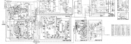
During fixing the Gm volume unit in this amp I shorted 2 pins marked on the schematic as C and D (+38.4 and -38.4VDC on the schematic bottom on the left) with the pin of DVM and the amp went completely dead, no lights, no relay click, nothing.
I found Q702 was internal shorted, after fixing it with new, no life in the amp again.
Main 4A fuse in perfect condition.
Primary and secondary windings of the transformer OK.
No part smells/looks burned.
I can see the thyristors or triacs on the schematic; do you have the idea how to check them? Probably they would not let to flow the current to regulated PS.
Please help troubleshoot the amp, this kind of power supply with the triacs instead of the fuses looks unfamiliar for me,
JVC AX-1100 - Manual - Stereo Integrated Amplifier - HiFi Engine if you are the member,
thank you in advance!
Attachments
Last edited:
Pavel,
I have a look in schematics and it looks like a regulated power supply.
I am supposing you do not have +38,4V and -38.4V
In Emitter of Q701 you must have +48V
In Emitter of Q702 you must have -48V.
Those voltages comes from a rectifier that do not appears in the partial schematics you posted. This is the first step in troubleshooting.
The control IC number IC701 is powered by +15V and -15V in pin 8 and 4 and theses voltages are generated by zeners diodes D703 and D704.
I hope you are familiar with multimeter operation and if these voltages appears it is possible the control IC is also damaged and need to be replaced.
It is a very nice and interesting amplifier.
I hope you success
Ronaldo
Pavel,
Those voltages comes from a rectifier that do not appears in the partial schematics you posted. This is the first step in troubleshooting.
Ronaldo thank you for the response!
all of the rectifiers are on the right, there are no more bridges; the arrow: TO SHEET 3 leads to secondary windings.
But anyway you are right, IC 701 and 051 are worth checking.
SF8D41 is TO-220AB/PKG SILICON CONTROLLED RECTIFIER 200-VOLT 8.0-AMP Do you have the idea how to check them with diode tester?
Hi!
R742 and 743 from the module ENH-097-2 are burnt,
so probably I found the reason of failure
anyway thak you for gazing!
R742 and 743 from the module ENH-097-2 are burnt,
so probably I found the reason of failure
anyway thak you for gazing!
after changing R742,3 the amp started, relay clicked!
so only broken channel of Gm pre left for fixing...
🙂
so only broken channel of Gm pre left for fixing...
🙂
FIXED!!!
Hi!
the amp is working!
Q701 was fried and 2 microtraces were broken near Gm selector.
I changed a few capacitors in Gm board,
the sound is superior with Magnepans Q1.5.
Highly recommended!
cheers

Hi!
the amp is working!
Q701 was fried and 2 microtraces were broken near Gm selector.
I changed a few capacitors in Gm board,
the sound is superior with Magnepans Q1.5.
Highly recommended!
cheers
Hi Pawel, team,
Good work! Let's party.
Yeah! Time for celebration!
Thank you Ina!
- Home
- Amplifiers
- Solid State
- Giant JVC AX-1100 dead, please help troubleshoot!