I finished building a 5F1 clone. Pretty happy with the results, especially with the cabinet and real leather handle.
But it doesn't sound right to me. My main concern is the lack of crunch - it's way to clean.
I guess high B+ voltage creates too much headroom, it's 20% higher than the suggested voltages on the old schematic.
Should I use higher resistances B+ or is there a better way to do it? (I heard some people use zener diodes).
Anything else I can do, to decrease the clean headroom? (except changing bias resistor).
Last edited:
Disconnect the 22k feedback resistor.
Then bypass the 1.5k cathode resistors with 22uF caps on the 12AX7 gain stages.
That should do it, you will have a nice amp that goes from clean to dirty with the roll of a guitar volume knob.
Then bypass the 1.5k cathode resistors with 22uF caps on the 12AX7 gain stages.
That should do it, you will have a nice amp that goes from clean to dirty with the roll of a guitar volume knob.
I'm already using a bypass cap on both tubes.
What I want to do is to play with different bias resistor values and also the feedback resistor, to get the best sound by ear.
But are the B+ voltages okay? Should I just stick with it, or is it best to lower them first?
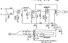
Voltages I'm measuring are in red.
What I want to do is to play with different bias resistor values and also the feedback resistor, to get the best sound by ear.
But are the B+ voltages okay? Should I just stick with it, or is it best to lower them first?
An externally hosted image should be here but it was not working when we last tested it.
Voltages I'm measuring are in red.
What is the voltage at the cathode of the 6V6? My guess is it's ~20v which at your voltages won't last very long.
Are you using a NOS 5Y3GT or a modern production one? The modern production ones have less voltage drop across them so you will want to use NOS.
Did you form a resistive divider at the cathode of the second gain stage where the feedback is injected? If not then the feedback probably isn't doing anything already, the cap is a low impedance path directly to ground effectively shunting the feedback.
What is the voltage at the cathode of the 6V6? My guess is it's ~20v which at your voltages won't last very long.
Are you using a NOS 5Y3GT or a modern production one? The modern production ones have less voltage drop across them so you will want to use NOS.
Did you form a resistive divider at the cathode of the second gain stage where the feedback is injected? If not then the feedback probably isn't doing anything already, the cap is a low impedance path directly to ground effectively shunting the feedback.
Yes, it's about 21V.
I'm using a modern Sovtek 5Y3GT, but I would like to make it work with modern production tubes if possible.
I did exactly what the schematics say concerning the feedback - but I do think feedback has an effect, because one of the issues I had when I first turned it on, was high volume squeal (leads on my OT have reversed color code).
Correction: I did not bypass the second stage, so the feedback should be okay.
Yeah I was going to say if you did bypass it the feedback shouldn't be working and something is wrong.
If you want to bypass the second stage this is what to do. This will maintain the same amount as original.
Also, I added in another RC filter in the power supply to drop B+ 35-50v. Since the amp is SE this will help reduce hum also.
Attachments
Yeah I was going to say if you did bypass it the feedback shouldn't be working and something is wrong.
If you want to bypass the second stage this is what to do. This will maintain the same amount as original.
Also, I added in another RC filter in the power supply to drop B+ 35-50v. Since the amp is SE this will help reduce hum also.
Yes, I wanted to add an additional filtering at some point, but forgot about it 😀
I installed a RC stage (1k/10uF), and it's down to resp 359V - 307V - 266V - 171V - 19.3V
Better, but I think I'll increase resistance a bit.
Would it be okay to use 22uF instead? (and 22uF + 10uF + 10uF which are already there). I heard tube rectifiers can't take as much capacitance as solid state rectifiers.
Disconnect feedback and add bypass cap there. Don't use Sovtek pseudo 5Y3. Add a screen resistor.
Would it be okay to use 22uF instead? (and 22uF + 10uF + 10uF which are already there). I heard tube rectifiers can't take as much capacitance as solid state rectifiers.
I use a 22uF cap after a 5Y3 in my guitar amps, datasheet specifies 20uF but remember caps back then had a very loose tolerance so 22uF is perfectly fine. To be more technical I feel it is a function of the HT secondary impedance that will limit current into the cap, take a reading with an ohm meter and run some sims in PSUD2. Instead of adding more resistance to the 1K RC filter you can additionally add series resistors feeding each plate of the rectifier tube from the HT secondary of the power transformer. This will lower B+ and help the rectifier live longer.
I still think if you want a dirty amp you will want to disconnect the feedback, there will be a much smoother transition form clean to dirty, not just clean then dirty. These amps when designed were meant to amplify cleanly😱
new jj 5y3s have correct 50v drop try one of those
Disconnect feedback and add bypass cap there. Don't use Sovtek pseudo 5Y3. Add a screen resistor.
Sovtek is all I have for now. I'll try JJ later.
Will 470Ohm do as a screen resistor?
I use a 22uF cap after a 5Y3 in my guitar amps, datasheet specifies 20uF but remember caps back then had a very loose tolerance so 22uF is perfectly fine. To be more technical I feel it is a function of the HT secondary impedance that will limit current into the cap, take a reading with an ohm meter and run some sims in PSUD2. Instead of adding more resistance to the 1K RC filter you can additionally add series resistors feeding each plate of the rectifier tube from the HT secondary of the power transformer. This will lower B+ and help the rectifier live longer.
I still think if you want a dirty amp you will want to disconnect the feedback, there will be a much smoother transition form clean to dirty, not just clean then dirty. These amps when designed were meant to amplify cleanly😱
I wanted to get B+ right first.
I did remove the feedback resistor, but now I get a buzzy kind of distortion. Not sure if I like it... sometimes it works, sometimes it doesn't.
Or maybe it's just my guitar (Gretsch G5420) - semi acoustics tend to have fuzzier distortion, but I made transistor pedals which sound much better - which shouldn't be normal. Sounds almost like something buzzing in the cabinet, but it's not. Sounds like electronic thing.
What could cause it to buzz?
Strange thing is, varying bias between 470ohm and 1000ohm on the power tube doesn't produce much difference sonically. I'm pretty sure I'm hitting the headroom.
I've been doing some measurements using different cathode resistors. Maybe it will be useful.
Rc = 476,1Ohm
Gave me 19,19V ground/cathode and 323,2V cathode/plate, 35,65mA current
= 13.02W of plate dissipation.
Rc = 605,2Ohm
Gave me 21,58V ground/cathode and 333V cathode/plate, 40,3mA current
= 11,32W of plate dissipation.
Rc = 903Ohm
Gave me 25,70V ground/cathode and 348,4V cathode/plate, 28,4mA current.
= 9W of plate dissipation.
Rc=476
19.19/476=40mA
Rc=605
21.58/605=35.65mA
I think you mixed up your results. BTW the current you are measuring through the cathode resistor is the combined plate and screen currents. You can use a 470R screen grid resistor right up against the pin is the best spot, when this is installed you can measure the voltage drop across it and then divide by the value, this will give you the quiescent screen current to deduct from the the cathode current to get actual plate current and actual plate dissipation.
For example with Rc=476 you get 40mA current through the cathode, but I am willing to bet 4-5mA of it is the screen current so you are actually probably only at 323*.0035=11.5watts plate dissipation. Which is within the 12watt rating.
Do you have an oscilloscope to look at clipping against a resistive load? This will help a lot if you do. I play semi-hollows (Collings Soco Deluxe, Gibson ES-335 etc...) and don't notice any bad sounding distortion from these sort of circuits. I have seen many tubes have an annoying rattle that cabinet vibrations set off, it can be very annoying. Try another set of tubes if you have some. You can also try lowering the amount of feedback, since you added more open loop gain you now have more negative feedback me thinks.
Rc=476
19.19/476=40mA
Rc=605
21.58/605=35.65mA
I think you mixed up your results. BTW the current you are measuring through the cathode resistor is the combined plate and screen currents. You can use a 470R screen grid resistor right up against the pin is the best spot, when this is installed you can measure the voltage drop across it and then divide by the value, this will give you the quiescent screen current to deduct from the the cathode current to get actual plate current and actual plate dissipation.
For example with Rc=476 you get 40mA current through the cathode, but I am willing to bet 4-5mA of it is the screen current so you are actually probably only at 323*.0035=11.5watts plate dissipation. Which is within the 12watt rating.
Do you have an oscilloscope to look at clipping against a resistive load? This will help a lot if you do. I play semi-hollows (Collings Soco Deluxe, Gibson ES-335 etc...) and don't notice any bad sounding distortion from these sort of circuits. I have seen many tubes have an annoying rattle that cabinet vibrations set off, it can be very annoying. Try another set of tubes if you have some. You can also try lowering the amount of feedback, since you added more open loop gain you now have more negative feedback me thinks.
Yes, it seems like I mixed up the figures.
I've been doing some reading on the internet, and it seems some people prefer much higher plate dissipation, 16W or even 18W - apparently the tubes can still take it in 5F1 (single ended), and it makes a better sound. (apparently, a good 6v6 will still survive years)
What do you think about it? Sure, this will increase the headroom even further, but I tried 300 ohm bias resistor, and it does give better sound (gives 14W of dissipation). Can't say how it sounds on max volume, but of 5-6 it sounds pretty good... clean but yet it does have a character. Strange, because higher dissipation increases the headroom.
Or maybe it's just my imagination.
Or maybe I do get grittier sounds because I removed the feedback resistor, even though the headroom has increased.
What I was hearing before, is not really a rattle - it just sounds like a bad kind of unmusical distortion (not in harmony with the sound).
My old scope recently died unfortunately (probably PSU caps gone bad). Should I bias for symmetrical distortion?
change the 6.8k feedback resistor to 3.3k and series a 5 or 10k pot for some interesting results. (presence control)
change the 6.8k feedback resistor to 3.3k and series a 5 or 10k pot for some interesting results. (presence control)
That is not presence control at all, that would just make the feedback adjustable. Presence control is lowering the amount of mid frequencies and up in the feedback loop in order to give them an overall boost.
Yes, it seems like I mixed up the figures.
I've been doing some reading on the internet, and it seems some people prefer much higher plate dissipation, 16W or even 18W - apparently the tubes can still take it in 5F1 (single ended), and it makes a better sound. (apparently, a good 6v6 will still survive years)
What do you think about it? Sure, this will increase the headroom even further, but I tried 300 ohm bias resistor, and it does give better sound (gives 14W of dissipation). Can't say how it sounds on max volume, but of 5-6 it sounds pretty good... clean but yet it does have a character. Strange, because higher dissipation increases the headroom.
Or maybe it's just my imagination.
Or maybe I do get grittier sounds because I removed the feedback resistor, even though the headroom has increased.
What I was hearing before, is not really a rattle - it just sounds like a bad kind of unmusical distortion (not in harmony with the sound).
My old scope recently died unfortunately (probably PSU caps gone bad). Should I bias for symmetrical distortion?
Yes these amps want to be run hot, they sound best that way. The JJ tubes can handle a bit more dissipation but for regular 6v6 types I usually stay around 12-14 watts depending on the tube.
You really should try and borrow a scope or use your computer but just attenuate the input with a resistive divider. That is probably the only way you will be able to see what is going on.
- Status
- Not open for further replies.
- Home
- Live Sound
- Instruments and Amps
- Getting more crunch out of 5F1 clone.