Hello friends.
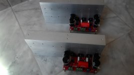
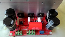
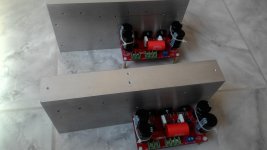
See photos of my LM3886 150w.
I'm feeding, with only a 250VA transformer. (25V + 0 + 25V) 10 amps.
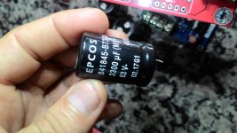
2 rectified source, with 40,000 UF, each source, one for each amplifier.
1 - Speaker protector
All resistors and capacitors with tolerance of 0.1%, I bought on ebay (seller petelex - England).
The problem:
I measured the individual DC offset, apparently at 13mv each.
I soldered the resistor 5W 0.2ohms.
Everything working and no buzzing.
However, one stove is getting very hot, the other is not heating up.
With the amplifiers on, I put my finger directly on the lm3886, I do not see much heat on a board. The other sign, everyone is getting quite hot.
What can this be?
I think:
DC offset setting, which was not correct.
Some output lm3886 is in trouble.
Or is it, that LM3886, is false? Seller sold me as original.
Now, what do you need to do to replace R7, R9 and R14, to test the DC offset again?
Any suggestion !!!
See photos of my LM3886 150w.
I'm feeding, with only a 250VA transformer. (25V + 0 + 25V) 10 amps.
2 rectified source, with 40,000 UF, each source, one for each amplifier.
1 - Speaker protector
All resistors and capacitors with tolerance of 0.1%, I bought on ebay (seller petelex - England).
The problem:
I measured the individual DC offset, apparently at 13mv each.
I soldered the resistor 5W 0.2ohms.
Everything working and no buzzing.
However, one stove is getting very hot, the other is not heating up.
With the amplifiers on, I put my finger directly on the lm3886, I do not see much heat on a board. The other sign, everyone is getting quite hot.
What can this be?
I think:
DC offset setting, which was not correct.
Some output lm3886 is in trouble.
Or is it, that LM3886, is false? Seller sold me as original.
Now, what do you need to do to replace R7, R9 and R14, to test the DC offset again?
Any suggestion !!!
Attachments
-
 P_20180409_211357.jpg945.6 KB · Views: 700
 -
 P_20180409_211413.jpg726.8 KB · Views: 655
 -
 P_20180409_211440.jpg857.3 KB · Views: 648
 -
 P_20180423_115109.jpg867.4 KB · Views: 611
 -
 s-l1600.jpg234.1 KB · Views: 306
 -
 P_20180423_115205.jpg837.2 KB · Views: 310
 -
 P_20180423_115158.jpg887.3 KB · Views: 276
 -
 P_20180423_115148.jpg915.1 KB · Views: 587
Did you see with oscilloscope if you have any oscillation at the output?
if you you connect only the main power +/- 25V rails without input signal and output wiring is it hot?
if you you connect only the main power +/- 25V rails without input signal and output wiring is it hot?
Sorry to burst your bubble, but you're not getting more than 110-120 W into 4 Ω from that amp. 55-60 W into 8 Ω. If the seller claimed 150 W, I'd consider that the first warning sign.
These numbers assume a ±35 V power supply. You can see my math here: LM3886 Output Power
It is possible that you received a fake LM3886, but I suspect the real reason for your trouble is that you have a poor thermal connection between the LM3886es and the heat sink. You need a dab of Wakefield 120, Arctic Silver, or similar thermal compound between each LM3886 and the heat sink.
I also suggest using a heat sink with vertical fins as it will dissipate the heat better. That said, what you have should be good enough for a prototype and I would expect it to be able to play music just fine at a reasonable volume without overheating. If you are testing with a sine wave and load resistors, you will need to address the issues in the thermal system.
In a parallel LM3886 amp, you can always test each channel independently by de-soldering the ballast resistor (0.1 Ω on the output). Test each LM3886, then connect them in parallel and test the parallel combination.
Don't forget that the DC offset needs to be adjusted before you mount the 0.1 Ω resistors. Short the input and adjust each trimpot such that you get 0.0 mV on the output of the amp. Use the mV range on your multimeter for this.
Tom
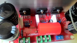
Those look like LM3886TF, TF being the plastic part and isn't as good at transferring heat though doesn't need insulating tab and bush.
Your smd components don’t look right. Looks like you swapped a cap and a resistor. The 200k resistor on the middle chip.
Also not being mean, but your soldering also looks suspect.
Also not being mean, but your soldering also looks suspect.
Last edited:
discovered the problem, refolded in smd and camacitor resistor, set DC offset of all outputs and set it to 0.
See youtube image below:
YouTube
Problem: When low volume has a buzzing sound, when the volume increases, it is not noticed.
I took the test, removing audio input. Tinnitus disappears. I believe it should be pre-amp grounding (Novo tom LM4610 + NE5532 Preamplifier amplifier board para diy hifi D3 006 em Amplificador de Eletronicos no AliExpress.com | Alibaba Group. 0.2742b90aTpXwRD).
Now I want to put this amplifier in jumper, I intend to use DRV134PA.
Last edited:
I finished building the amplifier LM3886tf - but, I have a doubt.
As shown on the board drawing I placed the 42pf capacitor (yellow circled design).
The device is working normally and well.
However, I have seen in other posts that there was an upgrade to 8pf instead.
The question, changing this capacitor, improves by what?
frequency?
Would this change be necessary?
Note: I myself did all the welding of the components.
Note:
I inserted the Thiele network.
RCA input noise suppressor.
Attachments

As shown on the board drawing I placed the 42pf capacitor (yellow circled design).
The device is working normally and well.
However, I have seen in other posts that there was an upgrade to 8pf instead.
The question, changing this capacitor, improves by what?
frequency?
Would this change be necessary?
Note: I myself did all the welding of the components.
Note:
I inserted the Thiele network.
RCA input noise suppressor.
Link videos youtube
YouTube
YouTube
YouTube
- Status
- Not open for further replies.
- Home
- Amplifiers
- Chip Amps
- Gainclone PA150