Hi all,
I've built my gainclone from chipamp.com's stereo LM3886 kit. The sound quality is amazing, tons better than my AV receiver, however unlike the receiver it has a tendency to make the speakers go "POP" whenever a light switch in the house is turned off.
The pop happens whether the input signal cable is plugged in or not.
My gainclone is the only device affected by this popping, and I'd be happy to hear any suggestions as to how to mod the GC to suppress the popping. The last thing I want to have to do is buy a UPS just for this purpose!
Thanks in advance.
Interference from lights being switched on can come from two sources.
1/ Through the mains into your equipment.
2/ Transmitted through the air as RF or EM into your equipment.
Theearthing can be perfect but if your PSU doesnt filter out spikes then the noise will still get through.
1/ Through the mains into your equipment.
2/ Transmitted through the air as RF or EM into your equipment.
Theearthing can be perfect but if your PSU doesnt filter out spikes then the noise will still get through.
Apparently chip amps are sensitive to voltage spikes on the mains. I built an lm3886-based amp and experienced the same problem. I replaced my AC receptacle with one that incorporated a filter and the problem was mostly solved. I say MOSTLY because if the voltage spike is high enough the problem still occurs. But this only happens now during electrical storms.
Yeah I found some of these filter IEC sockets on the Altronics website, unfortunately I've already put in the big IEC+fuse+switch one so the cutout is too big for the filtered unit 🙁
I bought a big orange metal powerboard from bunnings, that has filters in it apparently but didn't help at all.
Thankfully, Altronics has a mains filter kit which purportedly eliminates pops and spikes from entering the hi-fi system, at $42 it's expensive just to fix a few pops but it's the best option I have at the moment.
This of course assumes that the noise is coming from the mains! Although I really doubt it's coming from the line-in, since the pop is the same volume whether I have the volume set high or low... if it was an irregularity on the line-in, I'd imagine that the pops would increase with the volume.
Hi,
Most chipamp circuits major on how simple they are to assemble.
Consequently they omit many of the "normal" practice circuits/components that most designers fit as standard.
Have you fitted filters to the input end of the power amp? DC block and RF attenuator.
Have you fitted a filter to the speaker terminals? Thiele network.
Maybe RF sensitivity. Do you still have the problem ( or reduced) if you take the amp far away from that room and operate the same switch ?
Is your amp on a wooden base with no cover at all ?
Is your amp on a wooden base with no cover at all ?
if you built a true gainclone, it has no RF stopper on the input, so you will pick up the field.
The data sheet suggests 220pF between the inverting and noninverting input of the chip to prevent this.
The data sheet suggests 220pF between the inverting and noninverting input of the chip to prevent this.
A filter like this could be used:
http://www.rapidonline.com/Electron...s-Mount-Filters/Chassis-mounting-filter/64492
So you wouldn't need to change your inlet.
Check its shielded (ideally in earthed metal enclosure). If not, try and shield the inside of the box with foil/copper clad boards or at least use shielded wire for the input.
Add RF filtering at line in. Together should sort the problem out 🙂
It is very good that those cheaps are short term spikes responsive
this means will make the same with music..short term peaks will be listened into the music too...this can be also good.... not only annoying.
Will be interesting to me to know the solution you have found that this.
Good luck!
regards,
Carlos
this means will make the same with music..short term peaks will be listened into the music too...this can be also good.... not only annoying.
Will be interesting to me to know the solution you have found that this.
Good luck!
regards,
Carlos
I have a similar problem in my house. There is a store built into the house, so when one of the bigger coolers turn on i get a pretty loud pop through my speakers. I'm using a Hafler P230 and a Ashly FET-200 amp in a bi-amped setup. Installing IEC filter connections in both amps seems a waste if i could just install a filter myself.
Can i have a diagram of a simple rf filter for the mains?
Can i have a diagram of a simple rf filter for the mains?
Stormrider said:I have a similar problem in my house. There is a store built into the house, so when one of the bigger coolers turn on i get a pretty loud pop through my speakers. I'm using a Hafler P230 and a Ashly FET-200 amp in a bi-amped setup. Installing IEC filter connections in both amps seems a waste if i could just install a filter myself.
Can i have a diagram of a simple rf filter for the mains?
Attachments
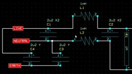
c3 & c4 are too large.nigelwright7557 said:
Reduce to about 2n2F to 47nF to keep earth leakage to acceptable levels. Earth connected caps must be Y rated as shown on the diagram.
AndrewT said:c3 & c4 are too large.
Reduce to about 2n2F to 47nF to keep earth leakage to acceptable levels. Earth connected caps must be Y rated as shown on the diagram.
You will need to scale down the components a bit as this was used with 110V and 30 amps !!! I just pinched it straight from an old project. It gave excellent results during EMC testing.
I solved it by placing 0.22u on each secondary, using long wires to connect the psu board to the transformer, giving these wires a few turns over a toroidal core taken from a computer smps and paralleling a small film cap with the first reserves. Some people said it was an useless practice as wire inductance is much larger than capacitor esl, but the wire inductance being high is what keeps spikes far away from the board.
I needed nothing else to get it quiet but, if it isn't enough you can add a noise killer taken from a computer psu and a TVS MOV (weren't these exactly to solve that problem?)
I needed nothing else to get it quiet but, if it isn't enough you can add a noise killer taken from a computer psu and a TVS MOV (weren't these exactly to solve that problem?)
ionomolo said:I solved it by placing 0.22u on each secondary, using long wires to connect the psu board to the transformer, giving these wires a few turns over a toroidal core taken from a computer smps and paralleling a small film cap with the first reserves. Some people said it was an useless practice as wire inductance is much larger than capacitor esl, but the wire inductance being high is what keeps spikes far away from the board.
I needed nothing else to get it quiet but, if it isn't enough you can add a noise killer taken from a computer psu and a TVS MOV (weren't these exactly to solve that problem?)
Good to know it is cured and was it mains born interference.
I get a loud pop through my speakers when my fridge switches on and off. I know what to do to get rid of it.
ionomolo said:I solved it by placing 0.22u on each secondary, using long wires to connect the psu board to the transformer, giving these wires a few turns over a toroidal core taken from a computer smps and paralleling a small film cap with the first reserves. Some people said it was an useless practice as wire inductance is much larger than capacitor esl, but the wire inductance being high is what keeps spikes far away from the board.
I needed nothing else to get it quiet but, if it isn't enough you can add a noise killer taken from a computer psu and a TVS MOV (weren't these exactly to solve that problem?)
Glad it works now! Not only does this solve your problem, but others may also learn from this when making their own amps..
I really like your method of wrapping the transformer output wires on a toroid a few turns before going to the bridge rectifier! You've inspired me to do that on my next amp project! 😀
IMO you can NEVER have too much filtering! 😀
Filters from computer PSU are great! Some PSU even have an extra inductor filter mounted on the back of the IEC input socket with a couple caps. When I built my amp, I used this filter, but added a HV 1uf cap across it for even more filtering. Then I ran that to a second inductor filter on the PCB with two more small caps, then it finally goes to the relay and primary coil of the transformer.
On the secondary side, I got a 0.1uf cap across the 2 AC terminals of the bridge rectifier, then where the DC runs to the amp, got two more HV 10nf caps. I've never had noise at all.
I've even stressed tested it by unplugging it in and out a bunch of times, and it doesn't upset it much. Besides the amplifier, there's a digital on/off control circuit for the amp, I sure didn't want any interference that could false-trigger it.
EWorkshop1708 said:
Glad it works now! Not only does this solve your problem, but others may also learn from this when making their own amps..
I really like your method of wrapping the transformer output wires on a toroid a few turns before going to the bridge rectifier! You've inspired me to do that on my next amp project! 😀
IMO you can NEVER have too much filtering! 😀
Filters from computer PSU are great! Some PSU even have an extra inductor filter mounted on the back of the IEC input socket with a couple caps. When I built my amp, I used this filter, but added a HV 1uf cap across it for even more filtering. Then I ran that to a second inductor filter on the PCB with two more small caps, then it finally goes to the relay and primary coil of the transformer.
On the secondary side, I got a 0.1uf cap across the 2 AC terminals of the bridge rectifier, then where the DC runs to the amp, got two more HV 10nf caps. I've never had noise at all.
I've even stressed tested it by unplugging it in and out a bunch of times, and it doesn't upset it much. Besides the amplifier, there's a digital on/off control circuit for the amp, I sure didn't want any interference that could false-trigger it.
My last two amp builds have been in PC cases.
I used the mains input filter.
The fan mountings are very handy for mounting fans to keep things cool.
The PC case is just the right size too and is strong enough to take a big toroidal transformer.
I go for the flat cases (not tower) so I can put a mixer on top of the amp.
nigelwright7557 said:
My last two amp builds have been in PC cases.
I used the mains input filter.
The fan mountings are very handy for mounting fans to keep things cool.
The PC case is just the right size too and is strong enough to take a big toroidal transformer.
I go for the flat cases (not tower) so I can put a mixer on top of the amp.
Very nice. Do you put your toroid inside the empty PSU case, or just the PC case itself? It's great that you use the filtering already provided by the PC PSU mains filter built in! 😀
- Status
- Not open for further replies.
- Home
- Amplifiers
- Solid State
- Gainclone makes my speakers go POP when lights turned off