I am working on a Marantz PM7000 with many issues, most of them are already solved. But I have a problem that it is literally driving me nuts. One of the amp channel, RIGHT CHANNEL, has a very low gain.
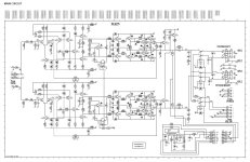
I first focused on the input differential amp, prior to measure, I checked transistors and fixed many cold soldering. The problem remained and I began to do some measures. As I have the other channel working I did, as usual, some comparative readings and on DC I can't find any difference from the good one to the failing other. Applying a 1 Khz signal I see the signal reaching R3316 and R3314 is very low if we compare it to the 3315 and 3313 on the Left Channel. And I am a bit lost, this are the challenges I like but, at this point, I think I need some fresh ideas as mines are on a loop. I have tested voltages, as mentioned, transistors (not with a cheap transistor tester but with a wonderful LEADER LTC-906A and a modern PEAK DCA75), diodes and resistors, even some capacitors that, to my surprise, were encapsulated as a resistor. First time I see this. The feedback is OK, power supply and limiting-protection resistors, everything is just fine.
Also, I didn't say it earlier, the signal reaching both channel inputs has the same level. I want to say this in case some may think I have any issues on tone or volume control, this is already fixed (there were some problems before)
I look forward for your experience and ideas because mine are exhausted. Thanks in advance
Attachments

Dear anatech:
Thanks for your reply and support. Not only I checked it already, it was a bit low on capacity but with a slightly high ESR so I replaced it and the problem is already there. I like to analyse, as far as my knowledge allows, the circuits and there are many things I can't understand on these diagram, one of them is the function of C2268 right after the BIAS transistor and the next stage.
Also, something I didn't mention but I believe is relevant, there is no distortion, there is a gain difference but both channels keep the signal with the perfect shape.
I enclose a better copy of the schematics for future references.
Again, thank you