Hello everyone! I have two xxlinside loudspeakers (an italian brand), model f212-p in which the two of the fuses on the pcb burnt three times in a row at the same time. I found nothing about the loudspeakers, but I disassembled one of them and I saw that in the pcb there's this code "pbm8amp", so I searched it and i found a mixer with the same exact pcb as the loudspeakers. As I was looking in the schematic I saw that the only thing that could cause the damage to both of the fuses (F2_1 and F2_2) is the bridge rectifier (D2_1). Am I right? I don't see anything except of the bridge that could blow the two fuses at the same time.
Here's the schematic: https://www.pdfhost.net/index.php?Action=DownloadFile&id=06bb80ff20b5902f14706c5d2e9d9856
And here's the part of interest of the circuit (page 13 of the pdf):

Here's the schematic: https://www.pdfhost.net/index.php?Action=DownloadFile&id=06bb80ff20b5902f14706c5d2e9d9856
And here's the part of interest of the circuit (page 13 of the pdf):
First of all.
If You have a dual supply, There should be a ground. I presume Both Output 2 are inter-connected. The bridge can be Ok, but it can be a inrush current problem when charging the PSU capacitors. There should be some current limiting circuitry involving a relay that shorts a high wattage resistor in series with the trafo during first ms power-up if You have a toroidal transformer. Have You tried slow blow fuses ? If there is a relay check if it's not stuck / welded contacts.
If You have a dual supply, There should be a ground. I presume Both Output 2 are inter-connected. The bridge can be Ok, but it can be a inrush current problem when charging the PSU capacitors. There should be some current limiting circuitry involving a relay that shorts a high wattage resistor in series with the trafo during first ms power-up if You have a toroidal transformer. Have You tried slow blow fuses ? If there is a relay check if it's not stuck / welded contacts.
First of all.
If You have a dual supply, There should be a ground. I presume Both Output 2 are inter-connected. The bridge can be Ok, but it can be a inrush current problem when charging the PSU capacitors. There should be some current limiting circuitry involving a relay that shorts a high wattage resistor in series with the trafo during first ms power-up if You have a toroidal transformer. Have You tried slow blow fuses ? If there is a relay check if it's not stuck / welded contacts.
Thank you for the reply. I checked the bridge with my dmm and it seems that it's working good, so I don't think it's causing the problem.

That should be the output amp section (page 13, on top of the page), could it be that the two 4700 uF electrolytic capacitors are causing the issue? Because I cannot see any relay in the circuit, I don't know how to move on with the troubleshooting.
Yes, I tried slow blow fuses and they burned up in the same way as the classic ones.
Did you check output transistors and predrivers (Q2:7 & Q2_8, Q2_1 & Q2_2), also check bias current wich flows through R2_23 & R2_24 (output emitter resistors). I suspect fault on these devices.
This amp has floating ground, generated by output transistors.
Bias is defined by D2_11, D2_12, Trimmer R2_16 and parallel NTC R2_8 (temperature dependent).
This amp has floating ground, generated by output transistors.
Bias is defined by D2_11, D2_12, Trimmer R2_16 and parallel NTC R2_8 (temperature dependent).
Did you check output transistors and predrivers (Q2:7 & Q2_8, Q2_1 & Q2_2), also check bias current wich flows through R2_23 & R2_24 (output emitter resistors). I suspect fault on these devices.
This amp has floating ground, generated by output transistors.
Bias is defined by D2_11, D2_12, Trimmer R2_16 and parallel NTC R2_8 (temperature dependent).
I will try it, thank you.
Another thing that I noticed is that the fuses mounted on the amp of the speaker are 8 amps, where, in the schematic of the service manual, it says that the fuses must be 4 amps (part 312 in BOM, says 4A 250V). Could the fuses be the problem?
no,
someone put the 8A, because 4A has blown.
You have obvious short circuit (probably output transistors).
someone put the 8A, because 4A has blown.
You have obvious short circuit (probably output transistors).
BIGGEST suspects are Power transistors TR93P and TR94N
And their drivers: Q2-1 and Q2-2
When dying they could have easily burnt/damaged Driver IC U2-1B , ballast resistors R2-23 and R2-24 plus R2-13 , R2-14 , R2-17 , R2-18 and assorted random parts around them.
With due respect and considering DEADLY voltages inside (146V DC rail to rail ) I strongly suggest you send amplifier to Official Service or equivalent.
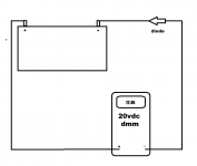
I often times test my diodes and bridge rectifiers by connecting them to a 9v or 12v small battery in series with my multimeter to read the voltage. On the bridge rectifiers, connect one side of the ~ input to the negative, then take readings on the + and - outputs independently. Repeat the process connected to the other ~ input with the voltage meter connected between the + battery terminal and the output pins, reversing the polarity of the probes to make sure voltage reads near full in the correct direction, but hopefully less than .1 volts in the other direction. Some diodes may pass from .2 to .9 volts in reverse bias, which is not very efficient, and should not be used. Blown diodes and rectifiers will pass almost the full voltages in both directions.
Attachments
To check for power supply failure disconnect power wires to amp and power up.
Big bang means power supply fault, no big bang means amplifier fault.
Its not too difficult to check power supply turned off.
Check bridge on your DMM diode function range.
Check capacitors for short circuit.
Big bang means power supply fault, no big bang means amplifier fault.
Its not too difficult to check power supply turned off.
Check bridge on your DMM diode function range.
Check capacitors for short circuit.
- Status
- Not open for further replies.
- Home
- Amplifiers
- Power Supplies
- Fuses keep burning, faulty bridge rectifier?