my question is: Can fuses at mosfets drains avoid devices to blow at fault conditions?
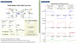
topology is half-bridge
mosfets are IRF730 - pulsed drain current are 22A
Vin = 310V
I think to place fuses for 6~10A at each drain
topology is half-bridge
mosfets are IRF730 - pulsed drain current are 22A
Vin = 310V
I think to place fuses for 6~10A at each drain
Attachments
If you are talking about installing fuses to prevent shrapnel in case of a failure then yes. You can also install on the input just before bridge.
yes fuse at main voltage (AC) is instaled. My question is about to install fuses at mosfets drains (Open circuit at same way but before the BIG capacitors discharge via drain-source blowing one or two mosfets)
maybe at transformer leg
maybe at transformer leg
During overcurrent conditions a high voltage MOSFET usually takes much less time to fail than a fuse to blow. Proper current sensing and active cycle by cycle current limiting is a much better way to avoid circuit damage in case of excess current.
The situation that you could avoid by adding a fuse after the capacitor bank is, for example, the cases of TO-220 switching devices exploding after they have failed, or some resistors burning. Note that there are also "fuse" resistors that will fail open in case of overcurrent rather than burning.
The situation that you could avoid by adding a fuse after the capacitor bank is, for example, the cases of TO-220 switching devices exploding after they have failed, or some resistors burning. Note that there are also "fuse" resistors that will fail open in case of overcurrent rather than burning.
thanks!
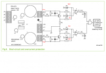
My last attempt to avoid overcurrent situation was a transformer to sense primary current, but which no good result.
Which the way most easy to implement the protection in the secondary one of a symmetrical source (protection for both rails)?
controler is SG3525 that acept pulse-by-pulse shutdown.
My last attempt to avoid overcurrent situation was a transformer to sense primary current, but which no good result.
Which the way most easy to implement the protection in the secondary one of a symmetrical source (protection for both rails)?
controler is SG3525 that acept pulse-by-pulse shutdown.
Eva´s full bridge battery charger
Hi Eva and SMPS masters
Eva, when I´m look your full bridge battery charger schematics, I think it don´t work because the conection of the mosfets gate to driver transformer it´s incorrect.
Regards
Hi Eva and SMPS masters
Eva, when I´m look your full bridge battery charger schematics, I think it don´t work because the conection of the mosfets gate to driver transformer it´s incorrect.
Regards
Please provide a link to the schematic or thread in question. Also, note that we are hijacking other people's thread 🙂
excuse me
Ok Eva
Tomorow I will post it, ok? In the last days I post a e-mail for you about.
Thanks
Ok Eva
Tomorow I will post it, ok? In the last days I post a e-mail for you about.
Thanks
>My last attempt to avoid overcurrent situation was a transformer to sense primary current, but which no good result.
Which the way most easy to implement the protection in the secondary one of a symmetrical source (protection for both rails)?
controler is SG3525 that acept pulse-by-pulse shutdown.
A current sense resistor (or shunt) or a hall effect current sensor can be used for DC current measurement. Current Sense transformers can't really be used with DC. If you need to monitor both outputs independantly you would need to use seperate current sensors with separate comparators to monitor current loads. The outputs from the comparators could be OR'ed together to trigger a shutdown in a overload condition. ie IF A is overloaded OR B is overloaded than shutdown. You might need to slew the input to address startup current demand or short term current spikes during operation that could trigger false overload conditions. This could probably be addressed with low pass filters.
Hi
Don't place them before C, then R nd C will form RC low pass filter, but won't be good for ripple. And you need anywhere form 1 to 2 v drop on that resistor to open opto, when it will open you can burn it, since it has no current limit (resistor) for diode...
Don't place them before C, then R nd C will form RC low pass filter, but won't be good for ripple. And you need anywhere form 1 to 2 v drop on that resistor to open opto, when it will open you can burn it, since it has no current limit (resistor) for diode...
Another question:
Fuses at outputs would serve of protection?
10A at +- cables
I imagine that fuses at output open before output caps discharge suficiently and current at primary increases very.
Fuses at outputs would serve of protection?
10A at +- cables
I imagine that fuses at output open before output caps discharge suficiently and current at primary increases very.
Hi
Don't worry about primary current as it can be few times bigger then normal + you will hopefully have fuse there too. Output fuse protect output device in case there is something wrong, like short circuit at output of amp, if amp doesn't have any overcurrent protection. I wouldn't go without those fuses too.
Don't worry about primary current as it can be few times bigger then normal + you will hopefully have fuse there too. Output fuse protect output device in case there is something wrong, like short circuit at output of amp, if amp doesn't have any overcurrent protection. I wouldn't go without those fuses too.
eltonseemann said:Hi Luka,
correction:
If unless the current sensor resistor has a significant resistance (bad) , I don't think there will be enough voltage drop to turn on the Opticoupler LED. A typical current sense resistor has a voltage drop measured in millivolts. You probably need some sort of amplifier to boost the voltage. A small signal NPN transistor could probably work.
Yes, with the opto I will need ~1.2V to detect overcurrent
for 8A limit I will need Rs = 0R15
this will dissipate even 9,6 watt at 8A DC or 3,4% of power
this is the worst case... 1.2V is 3.4% of 35V rail.
for 4A load, loss are 1,7% or 2,4W
for 2A loss are 0,8% or 0,6W
BC547 VBe(on) is ~660mV, little more than the half, but of the same order of magnitude
for 8A limit I will need Rs = 0R15
this will dissipate even 9,6 watt at 8A DC or 3,4% of power
this is the worst case... 1.2V is 3.4% of 35V rail.
for 4A load, loss are 1,7% or 2,4W
for 2A loss are 0,8% or 0,6W
BC547 VBe(on) is ~660mV, little more than the half, but of the same order of magnitude
- Status
- Not open for further replies.
- Home
- Amplifiers
- Power Supplies
- fuses for smps current protection