Im trying to understand why the designer of this amp. Used these components on the Phono Input.
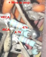
He has soldered the following components between the Phono in to ground.
To the positive pin he has soldered a 47K resistor. At the other end he has soldered a 4.7K resistor to ground.
Between the Positive and the negative he has a 3K3 ceramic cap. When I enter this up in the simulator it shows a drop of 10% in the input signal.
But there must be a reason for doing this. After looking at hundreds of Phono sections I do not see anybody else using this.
The 4.7K to ground seems rather low. Most other designs use 100K to ground.
Have included a pic.
Should I mod this or leave as is ?.
Attachments
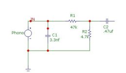
It is not very clear, a partial schematic diagram would help. It could be an input ground loop breaker (or something else).
Here is a basic schematic.
A friend who has a few more years in audio than I do (Just got started). Says it looks like a very basic loudness control.
The amp has 2 Phono inputs one is marked Ceramic with these components. And the other which is labeled magnetic. Without these.
When using the Magnetic input I notice that the amplification is much higher. And when using Ceramic with these components soldered to the RCA jack. The amplification is much less.
Should probably do a freq sweep and see if actually does anything to the signal based on Freq.
Attachments
Its all good and is as exactly as intended.
Ceramic and magnetic pickup are totally different things.
Magnetic is 2-5mV and requires riaa eq. Input is 47k ohm and few hundred pF.
Ceramic is line level, few hundred mV, and requires no eq.
Ceramic and magnetic pickup are totally different things.
Magnetic is 2-5mV and requires riaa eq. Input is 47k ohm and few hundred pF.
Ceramic is line level, few hundred mV, and requires no eq.
