I'm trying to understand what happens to a wave when it leaves a speaker. I believe that as a wavelength becomes small for the piston creating it, the radiation beams in a forward direction. From what I've read this might be because the piston pushes it that way.
On the other hand, as the wavelengths increase, the sound reaches out to the sides more. I'm guessing that this happens because distance sound travels during a cycle is greater. It has the chance to reach out during the cycle, like the woofer is acting more like a point source.
Am I on the right track?
To help me understand this, my question is...at higher frequencies where the woofer is beaming, does the sound wave actually touch the front baffle or simply launch away from the cone? or some combination?
In a somewhat unrelated question, does sound maintain its SPL over distance in an ideal wavetube?
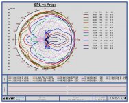
Here this might help you visualize what happens. Here is a software generated polar response on a 12" woofer.
Rob😀
Rob😀
Attachments

Last edited:
Thanks Robh3606. I guess what I'm really trying to understand is the dynamics of the wavefronts... and how they pertain to baffle design and baffle treatment.
Think of pressure waves being launched from every point on the diaphragm. If the diaphragm is larger, the distance from each point to your ear can vary by more than if the diaphram is smaller. When the wave from one "point" arrives so late that it has delayed by half a wavelength (pressure forward becomes pressure backward) relative to the pressure wave from another point, the opposite pressures from the two points cancel and no net pressure is left. At lower frequencies it takes a larger size (and difference in travel distances) for this kind of thing to happen. (this is a rather simplistic view, but I think contains the essence). WHen you are directly on-axis, the distance to every point is "most equal"
Last edited:
For the baffle, look at it slightly differently. Imagine a pressure wave going across the baffle. It can't go into the baffle, since that isn't compressible, so it rides out across the surface. Until it reaches the edge, where suddenly it is able to be relieved by going around the edge. This is equivalent to a pressure wave of inverse polarity being launched at the position of that baffle edge. The pressure there is reduced, which is the same as suddenly adding an inverse pressure to a non-inverse pressure. So that negative pressure wave propagates toward the listener as if it were another source. And of course, the distance from the driver to the edge will have different effects (launch an equivalent wave of different size and phase shift) depending on the frequencies of the wave being discussed.
One of the things I'd like to know (or preferrably understand😱) is whether the baffle receives some of these higher frequencies so that diffraction treatment is necessary. I suspected that the beaming meant there was no sound going sideways like that but from what you're saying, I'd guess there is?
I think you're saying that these point sources radiate omnidirectionally and the lobing is all about cancellations.
I think you're saying that these point sources radiate omnidirectionally and the lobing is all about cancellations.
I was reading something from Earl Geddes about this.
Notwithstanding my lack of understanding (and my paraphrasing🙄) I think he said that if the wavelength fits on the diaphragm it would be pushed only forward. This was a compression driver.
Notwithstanding my lack of understanding (and my paraphrasing🙄) I think he said that if the wavelength fits on the diaphragm it would be pushed only forward. This was a compression driver.
Paul Falstad's ripple tank simulator is useful for understanding diffraction.
I wrote a simulation of a flat baffle with a flat cone driver mounted on it, with a sealed back (no rear radiation). This simulates a typical sealed back tweeter on a baffle.
To use it, open this Web page:
http://www.falstad.com/ripple/
If you have Java enabled, an applet window should open with a wave animation in it.
Click "Stopped"
Click "Import / Export"
Click "Clear"
Paste the following 7 lines into the window:
$ 0 160 10 3 false false 15 15 600 1
s 85 128
s 115 128
c 25850 0
w 100 0
l 100
c 13950 0
Click "Import"
Untick "Stopped"
Vary the source frequency slider to see what happens.
I find it helps to click "Clear Waves" after moving the frequency slider by a large amount.
That app helped me to "see" what was happening. It does look like the points are omnidirectional and the beaming has to do with cancellation.
(Just thinking aloud) looking at Robh3606 plot it looks like anything above 4K doesn't have any energy at 180 degrees and anything below 640Hz is fully omni.
(Just thinking aloud) looking at Robh3606 plot it looks like anything above 4K doesn't have any energy at 180 degrees and anything below 640Hz is fully omni.
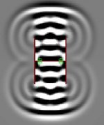
Don Hills, is it possible to use this wave simulator to show a horizontal cross section (looking down) on an 'H' frame?
Yes. Like this:
$ 0 160 12 3 false false 8 13 606 29
s 85 99
s 106 99
s 85 101
s 106 101
c 15880 0
w 1 0
l 30
w 1 0
l 4169
w 31 0
l 169
c 30 0
l 4169
c 15520 0
Note that the simulator only has monopole sources (point source or plane source). In order to simulate both sides of a speaker cone, you need two plane sources close together with a wall between them corresponding to the width of the cone. The sources have to be 180 degrees out of phase (the "Phase Difference" slider is all the way to the right).
Hmm, educational. The H frame seems to work well at low frequencies but at higher ones it suffers first from reflections off the inner walls, then diffraction off the tips.
OK, so maybe that was obvious. Seeing it really changes a person's mind. My first reaction was to want to burn them. I think I'll be damping the inner edges from now on. I think this may explain something about the sound.
Thanks all, I'm starting to get the hang of this.
OK, so maybe that was obvious. Seeing it really changes a person's mind. My first reaction was to want to burn them. I think I'll be damping the inner edges from now on. I think this may explain something about the sound.
Thanks all, I'm starting to get the hang of this.
In loudspeaker design you need to look at EVERYTHING with the relevant wavelength in mind. Almost nobody would use a H frame above the quarter wavelength of the front and back cavity. That means: At the upper frequency limit the cavity would inclose a quarter wavelength.Hmm, educational. The H frame seems to work well at low frequencies but at higher ones it suffers first from reflections off the inner walls, then diffraction off the tips.
... I think I'll be damping the inner edges from now on. I think this may explain something about the sound.
With the presettings of Rob his model will inclose 2 1/2 wavelength (that's 10 quarter wavelength). You need to draw the frequency slider far to the left before you get a realistic impression. No need to think about damping inner edges.
Attachments
Here's a screen shot of an H-frame FEA I did a long time ago:
This assumes the entire cone is moving in phase (no breakup).
Here's a U-frame:
There are polar plots in the same directories for each.
An externally hosted image should be here but it was not working when we last tested it.
This assumes the entire cone is moving in phase (no breakup).
Here's a U-frame:
An externally hosted image should be here but it was not working when we last tested it.
There are polar plots in the same directories for each.
These look goodHere's a screen shot of an H-frame FEA I did a long time ago:....
..but..
Rudolf said:Almost nobody would use a H frame above the quarter wavelength of the front and back cavity. That means: At the upper frequency limit the cavity would inclose a quarter wavelength.
... the H frames I have are 50cm across (1/4 @~ 170Hz) but I want to use them up to 1kHz.
Maybe I could line around the drivers, or convert to a rounded U frame and stuff the back?
1 KHz? Does the saying " Mate, you're dreamin' " sound familiar? 🙂
Lining or stuffing won't help much because the resonances you need to suppress are too close in frequency to the wanted frequencies. You can't suppress one and not the other.
Save yourself a lot of grief, and cross over at about 120 Hz to an OB midwoofer / midrange / tweeter (multiway or fullrange).
Have you read Linkwitz's series of pages "Issues in Loudspeaker Design", which are specifically about open baffles (flat, H, U shaped)?
Frontiers
- Status
- Not open for further replies.
- Home
- Loudspeakers
- Multi-Way
- Fundamentals of beaming and diffraction