Hi All,
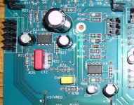
There are 2 opamps per channel on the driver board in my McCormack DNA0.5 amp. The one on the left is AD712 and the one on the right is NE5532. I've tried to go through the PCB trace but it look quite complicate. Don't know if these opamps function as DC-servo or not ???
If it does, will I get any improvement changing over from NE5532 to OPA2134 or OPA627 or it just a waste of money ?
🙄
Attachments
One op-amp, the 712 from memory, operates as a DC servo, the other is the error amp for the regulator for the driver stage.
I wouldn't change these willy nilly if I were you. The servo amp will need to have good DC parameters for a start and should be fet input. BTW it is a dual op amp.
Rob.
I wouldn't change these willy nilly if I were you. The servo amp will need to have good DC parameters for a start and should be fet input. BTW it is a dual op amp.
Rob.
Close Rob, but not quite.
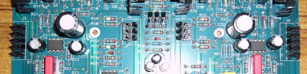
The AD712s (U1 and U2) are used as DC servos. They control the output DC offset to better than 1mV worst case and are difficult, but not impossible to improve on. The particular circuit topology used means that the opamp has less effect on the sound than is usually the case with DC servos.
Then there are two NE5532s. The LM833 opamp was also used in some versions.
The first (U3) is used to monitor the supply rails and senses if any of the supply rail fuses have blown. The second (U4) uses the first half of the dual opamp to sense any excess ouput DC offset while the second half sums the two error signals (blown fuse and/or excess output dc offset) and turns on a two relays if a fault condition occurs.
The relays mute the inputs and so ,hopefully, everything including yr speakers are protected ...
The supply rail monitor is isolated from the rail by 100k resistors so its hard to see that opamp effecting the rail. The dc offset monitor is isolated from the by resistors taht are 20x bigger than the one in the actual dc servo, so again, it is hard to see that having much sonic impact
Hi,
quite an achievement with one dual opamp.
Could someone post a schematic extract of the monitoring function? even a hand sketch would do.
quite an achievement with one dual opamp.
Could someone post a schematic extract of the monitoring function? even a hand sketch would do.
Thanks very much !
If I'm understand correctly, I should leave it as it is ?
And that's a wallet friendly choice 😀
If I'm understand correctly, I should leave it as it is ?
And that's a wallet friendly choice 😀
Hi Alan,
I believe you own the McCormack amp as well, right ?
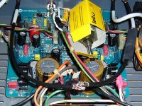
Here is existing condition of my driver board, noting morethan changing caps and mount the 10k attenuator directly between RCA & Driver board, what else I can do to make it sing better ?
Is is worth changing a rainbow cable that connect between driver & output board to a better one ?
Regards
Ball
I believe you own the McCormack amp as well, right ?
Here is existing condition of my driver board, noting morethan changing caps and mount the 10k attenuator directly between RCA & Driver board, what else I can do to make it sing better ?
Is is worth changing a rainbow cable that connect between driver & output board to a better one ?
Regards
Ball
I would leave the monitoring opamps alone. Those are U3/4. You could look for an improvement over the AD712 but I think your money is better spent elsewhere for there reasons outlined above.
I assume that you do not have the Deluxe version of the DNA0.5? In this case, you could consider doing what Steve McCormack did to make yr amp the Deluxe.
Change R1/R26(1k) to equivalent value Caddock resistors.
Change R2/R27(100k) to equivalent value Caddock resistors.
Change R10/12/25/27 (249ohms) to equivalent value Vishay resistors
Change R97/98 (154ohms) to equivalent value Vishay resistors
I do not recall if this change was in the Deluxe but I would also look for C13. This is 0.1 - 1.0uF capacitor. This cap provides a shunt around the Vbe multiplier. You want to replace this with a better grade film cap. This should have a voltage rating greater than 100V and you could fit yr current fashionable favourite.
But ... do NOT fit some weirdo audiophile cap that needs flying leads to connect it to the PCB. You need a cap that neatly fits where the old one used to be. I would cosider this nearly universal advice. You neither need some flakey cap in this circuit position that breaks off nor do you need an unhealthy injection of noise at this point.
So much modification work merely changes the noise spectral density. You want to improve the circuit operation not just change it.
Finally, note that to effectively and NEATLY perform these modifications you would need to completely remove the pcb from the chassis. Please use desoldering wick rather than a desoldering gun to reduce the likelihood of track/pad damage. And of course, you are on yr own if anything goes wrong!
Still want to get in there? 🙂
Hi Alan,
I stand corrected. Actually if I had looked at the photo I should have known the 5532 was not an error amp, since there were no
pass devices anywhere near it... Oh well my memory sucks.
Rob.
I stand corrected. Actually if I had looked at the photo I should have known the 5532 was not an error amp, since there were no
pass devices anywhere near it... Oh well my memory sucks.
Rob.
Hi Alan,
Thanks much !
Yes, I've the DNA 0.5 standard.
From the improvment I've got after changing all the stock caps to BG, I absulutely will give a try on changing resisters as well. 😀
My initial thought is to replace the 10 years old caps with a fresh one, and I found a positive comments about SMc's upgrade during searching for the info. about this amp. So, I end up with taking it apart and build it up again 😀

First, there will be a capacitor that corresponds to C13 on the other channel. Sorry, I forgot that.
The schematic shows just C13, but labels it as 0.1 to 10uF. So what you are seeing may well be a film cap of 0.1uF in parallel with a 10uF electrolytic. This would seem a reasonable compromise although the actual values are too far apart to prevent parallel resonances problems. These would only be obvious if you went looking with a network analyser.
Typically, you should parallel capacitor values that are separated by less than a factor of 3. This is not what is usually recommended in these DIY circles, but works best in my experience with the modern world with its EM fields.
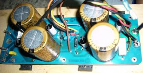
My apologies. The biasing network is on the output board - those are the two boards bolted to the heatsinks. So the cap in question is C13 on both these boards. The C13 that you are looking at is on the input/driver board and is the power supply decoupling cap for the negative rail of the DC servo.
Thanks very much Alan.
Sorry for confusing you, it doesn't have any mark on the pcb for a small cap. only for a large eletrolytic decoupling cap C1,C3,C5 and C7. But I believe the red wima cap on the middle of the board should be the one you talk about.
If you have schematic of this amp, is it possible to share with me. It would be a great help for my further tweak.
My email is "ballst22 at hot mail dot com"
Many thanks
Ball
😀
Attachments
No problem, some of this is done from memory. Some from a schematic and I also have one 'side, of a DNA1, that I got as a replacement spare.
I do not feel able to share the schematic without Steve's permission. Call me old fashioned, but it is a nice amp, largely well thought out and I think that that work/IP should be respected.
On a practical note, the schematic is printed from an inkjet and almost certainly reduced from at least A3 (if not A2) down to A4. So it is just legible as it is. Scanning would lose whatever details actually remain on the page. In fact, some of my problems figuring out yr question(s) was me trying to read the chicken scratchings of the schematic. And really can't be ar**d redrawing it in my CAD system. Sorry, but I'm too lazy.
But I'll scratch about in the archives, and see if I have someting better that could be scanned. Just don't hold yr breath.
Hi Alan,
Understand and I respect Steve's IP too. I actually plan to get the 2nd hand DNA1 of the States and ship direct to him for the upgrade & convert to monoblock, but it will take time for me to build a budget for that. The problem is after I start changing some caps and notice a big improvement... I just can't stop !
Sharing what you are comfortable to was already a big favor for me 😀
- Status
- Not open for further replies.
- Home
- Amplifiers
- Solid State
- Functional of opamps in McCormack amp