Hi Guys,
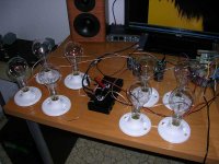
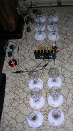
Just thought I'd post a picture of my half baked Son of Zen (SOZ) amplifier I built tonight instead of doing a PDE's assignment.
I've seen people use light bulbs as power resistors on the classic Zen series of amplifiers, but I'd never seen it done with the SOZ. I figured with the requirements put on the power resistors by this amplifier, it's a perfect candidate for lightbulb treatment!
I wasn't expecting much, but low and behold it turned out to be the lowest hum, best sounding low power amplifier I've ever heard. If you keep the volume within reason, it actually sounds better than my Aleph 2's. My wife also told me it looked very "Tesla", which I thought was kinda cool.
Anyhow, for anyone out there that has $60 to blow on 16 - 300W light bulbs and fixtures, this makes a pretty amazing one night project. I already had the mosfets on hand, along with a 500VA transformer, so I set it up with 25V rails to make a glorious 10 watts. It was one of those things that just fell into place.
Anyone have any ideas for a chassis this can go in?
Back to my assignment...
Owen
Attachments
Nice!
This must have been "the big fun amp"😀
If you intend to make a real amp out of it, I suggest you put a bigger heatsink for the mosfets, as the one on pic looks smallish. Capacitors don't seem particularly large as well, but if there's no hum, ok!
About the chasis, I just imagined two wooden vertical boxes, (two monoblocks) , with a somewhat larger base (to secure it from falllling down). Actually, they would look like two tall narrow floorstanders, except that instead of line array of speakers you'd have eight lightbulbs per channel😎
Just an idea..
regards,
Vix
Hi Owen,
That looks like fun. Did you get those bulbs in the Toronto
area? If so, can you tell me where? (I didn't find
anything useful the one time I looked at my local
Home Depot.)
Good luck with your PDE assignment!
Cheers,
Dennis
That looks like fun. Did you get those bulbs in the Toronto
area? If so, can you tell me where? (I didn't find
anything useful the one time I looked at my local
Home Depot.)
Good luck with your PDE assignment!
Cheers,
Dennis
opc said:Hi Guys,
Just thought I'd post a picture of my half baked Son of Zen (SOZ) amplifier I built tonight instead of doing a PDE's assignment.
I've seen people use light bulbs as power resistors on the classic Zen series of amplifiers, but I'd never seen it done with the SOZ. I figured with the requirements put on the power resistors by this amplifier, it's a perfect candidate for lightbulb treatment!
Owen
My lineup answer
is some weeks old
but we share the some idea 😉
😎 Sure is worth try.
As you say FUN! 😎
Posted: 1st December 2006lineup said:
I have praised the genius ZenLite by Pass several times before in this forum.
Besides, it is a spectacular amplifier to show to your friends
with that glowing bulb on top!
An externally hosted image should be here but it was not working when we last tested it.
I already had this idea, after thinking about this very thread yesterday:
Why not try the same concept for a Single Supply single ended Class A
PREAMPLIFER
Could be called
----------------------
PreLite
----------------------
I am already thinking about what lower wattage bulb
with a suitable resistance could be fit for such an amplifier.
Maybe something used in cars ... ??
Preferably should be a a light bulb with some nice and attractive colour.
😉
lineup
Link: http://www.diyaudio.com/forums/showthread.php?postid=1069576#post1069576
Hi Guys,
Thanks for the feedback! Vix, you're absolutely right about the size of that heatsink, it needs to be a little bigger, and needs to be mounted in a more appropriate position for air flow. It hits about 70 degrees (C) after two hours of use.
As for the capacitors and the power supply, I have no idea how it's working this well, but somehow it is. Infact the whole thing is terribly built, with the bias being off by a sizeable margin. Those caps are only 10,000 uF, giving a total of 40,000uF for the whole supply. If I built these properly, I'd use at least double that amount. As it is, the amp is magnitudes quieter than my Aleph 2's which have inductor coupled banks of 120,000uF. I'm listening to the amp on a pair of Lynn Olsen's Ariels, and at 92db/1w/1m I can't hear a thing with my ear 1" away from the tweeter. As for DC offset, it's also incredibly low at 0.04V without a speaker attached. I think I just got lucky with this though, as the bulbs and mosfets are not at all matched.
Dennis: Those bulbs are Phillips Clear 300W and I got them at Home Depot for about $3.60 CAD each. Once they heat up, two bulbs in parallel give about 10.5 ohms, so I really need to place another 100W - 200W bulb in parallel with the existing two to get down to 8 ohms.
Lineup: I love the layout! Looks just like my little ST-70. It's funny, the glow from the bulbs is almost appropriate give how close this thing sounds to a tube amp when you run it with a SE input. It's got that smooth midrange and twinkly top end that you only get from tubes. Maybe it's the poor damping (made worse by the 10.5 ohm bulbs) that gives it this qulity.
Anyhow, thanks for the tips, it's always fun to toss some junk together and have it work so well the first time you plug it in.
Cheers,
Owen
Common Mode Rejection Ratio, aka CMRR.
It's the ability of a circuit to ignore a common mode signal (i.e. something presented to both sides of the circuit...and yes, the rail voltage counts). Now, granted, the SOZ doesn't have a great CMRR, but it's better than nothing.
If you want to increase the CMRR, use a CCS under the differential. I started a thread on that once upon a time. You'll not only save heat, but you'll have more control over the bias.
Grey
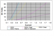
I don't know where everyone finds these low R bulbs??? I tested several again recently and the best bulb was a 300W GE clear (Home Depot) at around 27 ohms. Depending on the V and I of coarse...
I also ran into a 4500W 220VAC heating element for a water heater. So, I tested it too. The data is picture below 😀 It dosen't seem to have quite the heat sinking ability without the water but, it is more like a resistor😀
I also ran into a 4500W 220VAC heating element for a water heater. So, I tested it too. The data is picture below 😀 It dosen't seem to have quite the heat sinking ability without the water but, it is more like a resistor😀
Attachments
Light bulbs aren't particurarly linear as resistors. No surprise, given how they work. I asked Nelson how much distortion resulted; his reply as I recall was something along the lines of "not much."
Water heater elements, by their very nature, should be more linear given that they're not run into incandescence. However, they don't look nearly as cool. Might I suggest a bucket of water? An aquarium, better still. An inverted forest of these things in an aquarium could look interesting and would stabilize the temperature.
There are other things of potential interest, one being the resistive element out of a clothes dryer. Various items have been suggested over the years, but light bulbs still look the coolest.
Grey
Hi Grey
Nelson puts the PSRR of the SOZ at 26dB, but drawing a few hundred watts from that supply, I would have thought the ripple would be through the roof with only 20,000uF per rail.
As for the CCS, the whole point with the bulbs and stuff was to keep the thing simple and keep the heatsink size to a minimum. To be honest, I'm not sure the noise level of the amplifier could be any better than it is now. I've seriously never heard anything as quiet as this thing is, you'd swear it wasn't even on. An increase in efficiency would be welcome though, so maybe someday if I decide to go all out on it.
flg:
At the current and voltage I'm using, each 300W bulb looks like a 21 ohm resistor. I measured the current through each bulb and the voltage across it to get that value, so I'm sure about it. As you already know, the bulbs aren't at all linear, so as you up the voltage and current, the filaments heat up, and the resistance increases. My filaments are just barely glowing a dark red, so I'd imagine if you pushed them harder, the resistance would increase quite a bit. I did some calculations, and I think two 300W and a 200W in parallel would give you about 8.3 ohms for the drain resistors, and two 300W and a 100W in parallel would give you 9.0 ohms for the source resistors. This would give you exactly what Nelson spec'd in the original design, and a 25V supply means you get 10 watts of output. I'm going to buy the extra bulbs today and give it a try.
The part of this design that I find the most interesting is that the power output is now only limited by the power supply and the heatsink size / power handling of the fets. Those bulbs are good for 300W each, so if you wanted to make a 100watt SOZ, the bulbs would be more than up for it!
Maybe if I run across a 3KVA supply at the right voltage, I'll give it a try... or not.
Cheers,
Owen
Attachments
26dB is 20x reduction. Not too shabby. You can push that way, way up with a CCS if you want, but it sounds like you're happy where you are.
20000uF per rail is a decent start. Quoting from memory, I believe the Hafler DH-200/500 used 10000uF per rail (yeah, yeah, I know...60V rails, less bias current...details, details...still...). How effective it is at filtering is going to be a function of a bunch of factors. Just for giggles, measure the ripple.
Grey
It'd be interesting to have matched dual power MOSFETs--something along the lines of a hefty 2SK389/2SJ109. All the duals I'm aware of are little dinky things.
Grey
Grey
SOZ update
Hey Guys,
Well, I went and picked up the last few bulbs I needed and gave the SOZ another try with lower resistance values. Looks like my matching luck is up, as the DC offset is up to 0.6VDC. Not really acceptable, so I'll have to move some bulbs around and maybe get closer to the value I had before.
The power supply measures pretty badly, as I suspected. It's down to 20.8VDC per rail with the lower resistors (bulbs), and 0.368VAC ripple. At around 1.75% I'm not very impressed, but the circuit rejects it exceptionally well producing only about 3mv of AC on the output with no load. It's still completely inaudible.
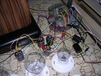
The bass is quite a bit better with the new bulbs, and the voices don't lose composure under bass transients at higher volumes. The bias was so far off before that the amplifier was clipping early at higher volumes. It actually plays very well for an amp that puts out less than 10 watts, and probably has an atrocious damping factor driving the 4 ohm Ariels. For the first time ever the impedance compensation network on the speakers is clearly audible. You can see the LRC circuit in one of the pictures I posted along with the switch I use to turn it on and off. The Aleph's don't mind the reactive load, but my little summer tube amps do, hence the switch. With the SOZ the network sounds like a midrange brightness switch, either forward and bright with it on, or recessed and dark with it off. If anyone knows why this is, I'd love to hear it.
I'll play with the amplifier a little bit more tonight and see if I can't get the offset a bit lower. The mosfets are also cooking hot now, but hopefully they'll hold up for testing. The heatsink measures in at a little over 170F so they probably aren't too happy.
With a little bit of work I'll get the equivalent resistance of the bulbs and report back. I don't feel like breaking up the circuit right now to measure the current into each leg. Any more comments are welcome, electrical or otherwise.
Grey: You're right about the matched power mosfet thing, it really would be nice! I guess the heat dissipation would be a problem, but with a big enough package you could overcome that. Oh well, for now the little on-semi devices will have to do.
Cheers,
Owen
Hey Guys,
Well, I went and picked up the last few bulbs I needed and gave the SOZ another try with lower resistance values. Looks like my matching luck is up, as the DC offset is up to 0.6VDC. Not really acceptable, so I'll have to move some bulbs around and maybe get closer to the value I had before.
The power supply measures pretty badly, as I suspected. It's down to 20.8VDC per rail with the lower resistors (bulbs), and 0.368VAC ripple. At around 1.75% I'm not very impressed, but the circuit rejects it exceptionally well producing only about 3mv of AC on the output with no load. It's still completely inaudible.
The bass is quite a bit better with the new bulbs, and the voices don't lose composure under bass transients at higher volumes. The bias was so far off before that the amplifier was clipping early at higher volumes. It actually plays very well for an amp that puts out less than 10 watts, and probably has an atrocious damping factor driving the 4 ohm Ariels. For the first time ever the impedance compensation network on the speakers is clearly audible. You can see the LRC circuit in one of the pictures I posted along with the switch I use to turn it on and off. The Aleph's don't mind the reactive load, but my little summer tube amps do, hence the switch. With the SOZ the network sounds like a midrange brightness switch, either forward and bright with it on, or recessed and dark with it off. If anyone knows why this is, I'd love to hear it.
I'll play with the amplifier a little bit more tonight and see if I can't get the offset a bit lower. The mosfets are also cooking hot now, but hopefully they'll hold up for testing. The heatsink measures in at a little over 170F so they probably aren't too happy.
With a little bit of work I'll get the equivalent resistance of the bulbs and report back. I don't feel like breaking up the circuit right now to measure the current into each leg. Any more comments are welcome, electrical or otherwise.
Grey: You're right about the matched power mosfet thing, it really would be nice! I guess the heat dissipation would be a problem, but with a big enough package you could overcome that. Oh well, for now the little on-semi devices will have to do.
Cheers,
Owen
Yes, the .368V can be improved, but for a knock-together amp I think you're doing pretty well.
170 degrees is getting pretty rough. Put a fan on your heatsink. Even if it's only turning at half speed, it'll move some heat. It'd be a pity to roast your devices. I used to wire two of the old-style Boxer cooling fans in series. They'd start reliably and run quietly. Of course, living with mainframe computers, I had a box full of them to play with. Still have some, I think.
I have no Earthly idea what the percentage tolerance on light bulb resistance might be, but it stands to reason that you should be able to mix and match and get something that balances on each side.
Grey
Nearing completion...
Hi Guys,
Thanks for the heads up Nelson, I wound up using a 22 ohm in parallel with one of the 1 ohm resistors to end up with about 45mv of DC offset. I could have kept messing about with it, but I got tired of walking to the resistor bin. I guess a pot would be the better choice here, like you mentioned in your article.
Grey's idea about swapping the bulbs was also my first inclination, but it's a little too much of a guessing game. After swapping bulbs for 10 minutes it got as bad as 1V, and as good as 200mv, but the parallel resistor provides a more predictable approach.
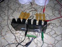
As for the hot heatsink, it was actually a major screw-up on my part. Those light bulbs are a lot less linear than I though, and when I used the two 300W bulbs with the one 200W I wound up with 5 ohm drain and source resistors. The current was way too high , and the fets were getting way too hot. I finally settled on a pair of 200W bulbs in parallel with a 100W, which gives a final value of 7.72 ohms in my setup with 21 volt rails and 1.9A per leg. The amplifier is now double the length it started at, but it's perfectly biased and running well in the safe zone with the fets at 140 degrees F.
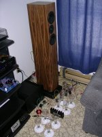
I'm actually so happy with the way it sounds that I'm going to put it in some sort of chassis and spend the money on a second set of bulbs to make the other channel. I have a second transformer and more caps, so I might as well go the whole nine yards. I bypassed the PS caps with some 5uF polypropylenes for fun, and the rest of the amplifier is exactly as per the original article.
I'll toss in a few final pictures of the complete prototype, which now spans 4 feet across the very ugly living room floor. I guess as a side project I should write a paper on how not to wire an amplifier. Hopefully nobody on here with call CSA on me. As always, keep the suggestions coming!
Owen
Hi Guys,
Thanks for the heads up Nelson, I wound up using a 22 ohm in parallel with one of the 1 ohm resistors to end up with about 45mv of DC offset. I could have kept messing about with it, but I got tired of walking to the resistor bin. I guess a pot would be the better choice here, like you mentioned in your article.
Grey's idea about swapping the bulbs was also my first inclination, but it's a little too much of a guessing game. After swapping bulbs for 10 minutes it got as bad as 1V, and as good as 200mv, but the parallel resistor provides a more predictable approach.
As for the hot heatsink, it was actually a major screw-up on my part. Those light bulbs are a lot less linear than I though, and when I used the two 300W bulbs with the one 200W I wound up with 5 ohm drain and source resistors. The current was way too high , and the fets were getting way too hot. I finally settled on a pair of 200W bulbs in parallel with a 100W, which gives a final value of 7.72 ohms in my setup with 21 volt rails and 1.9A per leg. The amplifier is now double the length it started at, but it's perfectly biased and running well in the safe zone with the fets at 140 degrees F.
I'm actually so happy with the way it sounds that I'm going to put it in some sort of chassis and spend the money on a second set of bulbs to make the other channel. I have a second transformer and more caps, so I might as well go the whole nine yards. I bypassed the PS caps with some 5uF polypropylenes for fun, and the rest of the amplifier is exactly as per the original article.
I'll toss in a few final pictures of the complete prototype, which now spans 4 feet across the very ugly living room floor. I guess as a side project I should write a paper on how not to wire an amplifier. Hopefully nobody on here with call CSA on me. As always, keep the suggestions coming!
Owen
Attachments
- Status
- Not open for further replies.
- Home
- Amplifiers
- Pass Labs
- Fun with Lightbulbs and the SOZ...