Preparing a paper about active feedback, sharing these counter-intuitive results might give some insight in the operation of amplifiers.
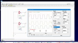
Shown in the illustration, IOP1 and IOP3 (Tina-TI simulation, IOP='ideal opamp') have their inputs swapped, but not the active feedback operational amplifiers IOP2 and IOP4. The feedback network consisting of R2 and R3 are identical.
Both circuits behave as inverters, what was not immediately expected with the IOP1/IOP2 configuration, whereas it was obvious with the IOP3/IOP4 configuration.
To avoid lengthly derivations of formulas, consider the outputs of IOP2 and IOP4 as "Vz", being -(R2/R3)* Vout.
For the IOP1/IOP2 configuration, Vout = Ao * ( Vin - Vz ), which boils down to Au = -R3/R2!
For the IOP3/IOP4 configuration, Vout = Ao * ( Vz - Vin ), which boils down to Au = -R3/R2!
Concluding that not the forward configured amplifier (IOP1, IOP3) determines the overall performance, but the active (in this case) controller (IOP2, IOP4).
Notice that amplifiers in general behave less then perfect at extremes (high frequency, start up / shut down sequences, to name just those two), and the poltergeist Murphy (In Ravels Gaspard de la Nuit named Scarbo) can pop up everywhere, mostly quite unwanted...
Other more developed similar circuits (a passive feedback in IOP1/IOP3 or non-inverting feedback controlling IOP2/IOP4) show none to less favourable solutions, as a simple resistive divider and a buffer has proven already.
And I promised N. Pass a headstart, so here it is.
R1 is left out (obvious, no real zener here), μ is approx (R3/R2)^2.
Attachments
Last edited:
Perhaps their "ideal opamp" is a nullor, rather than an actual opamp model? Nullors are theoretical tools that just solve the equation Vin+ = Vin- without any regard to stability.
I used this IOP for clearity - it als works with regular opamps, and in real life with real components, like bjt's, jfet's and mosfets.
Ah you've fallen into a trap, look carefully at resistor ratios and the very different voltage axes... The simulation is showing nullor solutions, which in one circuit is non-physical as its unstable. I'm going to reproduce in LTSpice for comparison...
So in LTSpice, real opamp models, voltages scaled to be +/-15V friendly:


So one has gain 100/1.5 and the other is latched up, as I'd expect.
So one has gain 100/1.5 and the other is latched up, as I'd expect.

VF3 looks legit and consistent with reality but VF1 looks like a sim artifact. It looks physically impossible, and I am pretty sure that if you breadboard it, it will behave as a schmitt trigger.
In an AC analysis, such a circuit can appear to work, but not in transient mode, unless there are simulation quirks, or invisible opamp properties
In an AC analysis, such a circuit can appear to work, but not in transient mode, unless there are simulation quirks, or invisible opamp properties
Yes, exactly, and if you sufficiently increase the amplitude of V1, you should observe the schmitt trigger behaviour.So one has gain 100/1.5 and the other is latched up, as I'd expect.
Not necessarily.
Once it is latched up, you may need to remove power to get it out of that state.
Depends also on the type of opamp.
Jan
Once it is latched up, you may need to remove power to get it out of that state.
Depends also on the type of opamp.
Jan
You don't really need nullors, ideal controlled sources with finite gain also work fine with positive feedback, even when the loop gain is far above one. They have no poles to shift into the right half plane, hence no instability.
By the way, the whole thread reminds me of this one:
https://www.diyaudio.com/community/...the-flaw-in-its-behaviour.400390/post-7379529
The circuit in there obviously had two latch-up states, but it could also be in a state where it actually worked.
https://www.diyaudio.com/community/...the-flaw-in-its-behaviour.400390/post-7379529
The circuit in there obviously had two latch-up states, but it could also be in a state where it actually worked.
Revisited.
Many thanks for all the constructive contributions!
Replaced the timed generator output to a simple sine, the opamps only the humble 741's.
The positive input (upper one) is stuck to the negatieve rail - this won't work in real life.
So after elaborate calculations at my desk, where things proove right, the silicium halts me to a no on this one.
If wanted, I'll post my hand-written notes (captures) also about the flawed pos-input variation.
Just happy to notice the active controlled inverter acts as expected, as this counts for the above mentioned link in #1.
Attachments
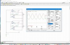
This sim illustrates the non-inverting, schmitt-trigger behaviour of the circuit, when driven by a sufficiently large input signal:

Well spotted! Here though the "ideal opamp" being a nullor has infinite gain (of either sign) and Nyquist's criterion doesn't get a look in.By the way, the whole thread reminds me of this one:
https://www.diyaudio.com/community/...the-flaw-in-its-behaviour.400390/post-7379529
The circuit in there obviously had two latch-up states, but it could also be in a state where it actually worked.
- Home
- Design & Build
- Electronic Design
- Fun with active feedback!