Member
Joined 2016
1200 W?
How can you get 1200 W if you supply it with 55 V?
If you do some calculations: (55 V * 55 V) / 4 Ohm = about 750 W peak, in the best case without considering losses.
1200 W RMS can be obtained by supplying about 70 V plus and minus, so 140 V peak to peak.
Let me know
How can you get 1200 W if you supply it with 55 V?
If you do some calculations: (55 V * 55 V) / 4 Ohm = about 750 W peak, in the best case without considering losses.
1200 W RMS can be obtained by supplying about 70 V plus and minus, so 140 V peak to peak.
Let me know
How can you get 1200 W if you supply it with 55 V?
If you do some calculations: (55 V * 55 V) / 4 Ohm = about 750 W peak, in the best case without considering losses.
1200 W RMS can be obtained by supplying about 70 V plus and minus, so 140 V peak to peak.
Let me know
You should do your calc with +-55V supplies😉
You should do your calc with +-55V supplies😉
Yup, I'm sorry hahaha
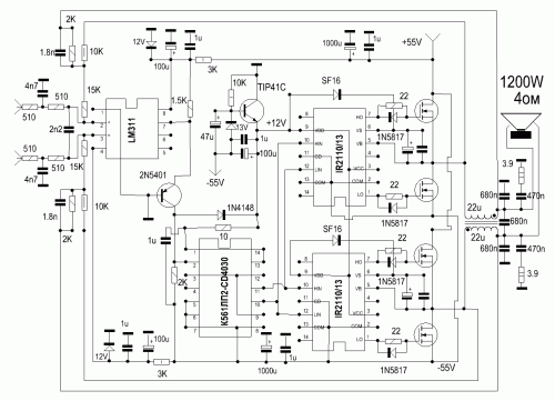
Please anybody check this circuit diagram.Is it ok or not ?
I activate the subject again to have your own opinion on the circuit.
Do you think this diagram will work?
Thanks!! 🙂
I would call this the latest crap from a dismissed audio member😀go to
Indonesia Next Generation Class D FB Group
and you will learn the secrets of Class D
go to
Indonesia Next Generation Class D FB Group
and you will learn the secrets of Class D
residual echo. 😛
I would call this the latest crap from a dismissed audio member😀
Can you offer alternative tested circuits that have already been built by a large number of members?
I don't think you have anything
residual echo. 😛
I don't think you have anything
otherwise you would share it here in the forum
I prefer quality from quantity. And for your info, I do not share any commercial interests in audio. If you are interested in my contributions here the search engine is your friend.🙂
> I do not share any commercial interests in audio. Ha Ha lol
> I would call this the latest crap from a dismissed audio member
Class D is no longer DIY
Yes, I can only laugh, the "DISMISSED AUDIO MEMBER" stands in the way of some commercial interests, since the previous commercial salespeople are afraid of the sale, since poorly developed circuit rubbish due to new competition is no longer as easy to sell to the end customer as before is.
Keep your commercial secrets to yourself, Pandora's box is wide open to educate and train new competitors, these will come very soon and will share their knowledge with others.
I have no doubt that class-D is no longer DIY for you - but this holds not true for everone, me for instance.
Certainly you can prove your claims by links to the companies who see a competitor in your asian class-D god.
Certainly you can prove your claims by links to the companies who see a competitor in your asian class-D god.
I activate the subject again to have your own opinion on the circuit.
Do you think this diagram will work?
Thanks!! 🙂
I think the OP didn´t get the answer he wanted because he used a
TOO SMALL FONT
😛 😛
As of the circuit, as shown it can´t be built.
* missing component values
* missing layout and assembly instructions
* missing PCB
* even if "working" , it needs vital elements, specially on the protection area, and it would nice to add something protecting speakers from catastrophic amp failure.
**MISSING POWER SUPPLY DESIGN.**
Unless you want to power it from 15 kilograms of iron and copper plus a shoe box worth of capacitors, which would kind of defeat the purpose of going Class D
Again: Class D PCBs take a lot of experience to design, so besides basic black and white artwork, designer "should" provide proper Gerbers so builder can order usable PCBs from some established supplier.
A few experienced designers and builders can fill the (many) missing dots on their own, no doubt, but I don´t see that bare incomplete schematic as much helping an average DIYer.
Please anybody check this circuit diagram.Is it ok or not ?
Dont build it go learn in FB group
I built this amplifier and its working. Output power was 900w sinus at 1kz with 50-0-50 power suply.
Do you have any pictures of the tests performed?I built this amplifier and its working. Output power was 900w sinus at 1kz with 50-0-50 power suply.
Thanks,
- Home
- Amplifiers
- Class D
- Full Bridge Class D 1200 watt Audio Amplifier
