2.5A DHT heater supplies adjustable between 2.5-7.5V internally limited at 4A. However the dissipation limit of the transistor makes them unsuitable for tubes like the 211/845/GM70
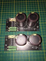
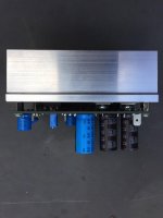
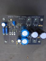
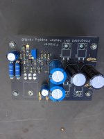
These are some of my DIY DHT heater supplies. They are one of the earlier versions without a "pre-regulator". Therefore they are quite low drop.
The topology is that of a voltage controlled current source, that should be outside of the audio spectrum from 20Hz onwards.
They are handmade to my own design, and tested and adjusted to 5.0VDC. Their dropout is about 1.5V at 1A. And their noise+hum is about 500uV/.5mV RMS measured with a Fluke 175 at 500,000 uV (or .5V RMS) ripple on the input.
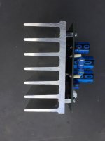
Permissible dissipation is around 15W on the heatsinks pictured, those are 2.3K/W types. Something that doesnt even come close to the dissipation required to glow a 1.5A 300B at 7.5VDC input. (approx 4W).
Connections are by means of 6.3mm faston spade connectors, i will include a dozen of those as well.
Pros:
I also have a pair suitable for both 211 or GM70 tubes, these feature the same heatsink but a more expensive opamp and TO247 fet instead of the TO220 transistor on these.
Asking €50 for a pair, and an extra €20 for two CLC rectifier boards. If you order these i can supply extra boards and parts at cost of my new design. Which features a Linear regulator as pre-regulator for lower noise.
Payment: paypal is preferred, shipment through DHL, please inquire about shipping rates beforehand if your outside of the EU.
These are some of my DIY DHT heater supplies. They are one of the earlier versions without a "pre-regulator". Therefore they are quite low drop.
The topology is that of a voltage controlled current source, that should be outside of the audio spectrum from 20Hz onwards.
They are handmade to my own design, and tested and adjusted to 5.0VDC. Their dropout is about 1.5V at 1A. And their noise+hum is about 500uV/.5mV RMS measured with a Fluke 175 at 500,000 uV (or .5V RMS) ripple on the input.
Permissible dissipation is around 15W on the heatsinks pictured, those are 2.3K/W types. Something that doesnt even come close to the dissipation required to glow a 1.5A 300B at 7.5VDC input. (approx 4W).
Connections are by means of 6.3mm faston spade connectors, i will include a dozen of those as well.
Pros:
- Big heatsink.
- short circuit proof for short periods of time.
- Good noise performance
- bulky heat sink that is rather hard to mount because you need to drill your own holes in the heatsink.
- Needs external rectifier plus capacitor board to function.
I also have a pair suitable for both 211 or GM70 tubes, these feature the same heatsink but a more expensive opamp and TO247 fet instead of the TO220 transistor on these.
Asking €50 for a pair, and an extra €20 for two CLC rectifier boards. If you order these i can supply extra boards and parts at cost of my new design. Which features a Linear regulator as pre-regulator for lower noise.
Payment: paypal is preferred, shipment through DHL, please inquire about shipping rates beforehand if your outside of the EU.
Attachments
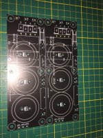
Photo's capacitor boards.
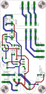
These are the capacitor boards available with the modules.
They are simply a SB540 skottkey bridge, followed by 22000uF 25V then a 500mOhm resistor and another 22000uF cap, these feature soldering pads for 18AWG wire.
Dimensions are 50x120mm with 4.3mm holes 5mm from each side.
I can also supply these PCB's.
Attachments

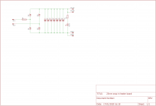
555 time delay's assembled and tested.
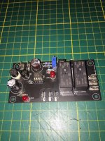
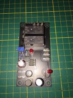
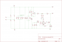
These are dual relay 555 timer delay PCB's that can be fed directly from the 6.3VAC present in your amplifier.
These work in the following manner: once you apply 6.3VAC between J1 and J2 the timer capacitor will charge, and once this charge reaches 2/3VCC the output of the 555 will go high, and the relays will be turned on by the BD139 driver.
The relays are capable of switching 250VAC 16A loads, and their maximum spec says 440VAC.
See the attached schematic, the time is adjustable with the little 25 turn potentiometer. with the component values on this lot the time is adjustable roughly between 20-30s
Asking €20 for one assembled and tested module.
Attachments

Last edited:
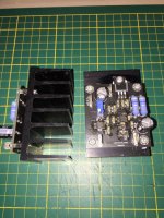
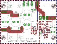
FET based DHT regulator complete with rectification
This is a pair of FET based regulators for 211/845 tubes. These function as a constant current source that is high impedance in the audio frequency range.
Adjustable between 2.5-15V with a minimum of 7.5VDC in and internally limited at 4.2A.
These feature an on board bridge made up of four TO220 BY29-50 diodes. And ive used the capacitors i had at hand: 4X 2200uf 25V, this is inadequate for 3.5A of output current, that's why there are two faston connectors labeled elco+ and resp elco- that allow you to connect an external capacitor or bypass the on- board rectification altogether.
Suggested operation conditions for 211/845 tubes are: 12VAC in. 10VDC out. at 3.5A continuous.
The heat sink is somewhere in the ballpark of 1.5K/W and the FET doesnt really care for high heatsink temperatures as its a L2 series linear device that will survive pretty much anything you can throw at it in this application.
For those interested the part number is : IXTH80N075L2
Datasheet here: https://m.littelfuse.com/~/media/el...n-channel_linear_ixt_80n075_datasheet.pdf.pdf
Asking €70 for a assembled and tested pair.
Attachments


Universal HV boards
These are "Universal" boards for the high voltage in tube amps, or they can be used for low voltage CRCRC filtering.
Two for €12.50
These are "Universal" boards for the high voltage in tube amps, or they can be used for low voltage CRCRC filtering.
Two for €12.50
Attachments


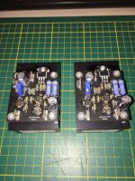
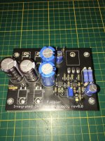
Some additional photo's of the integrated regulators
I made some additional photo's in daylight.
Price on these reduced: €60 for a pair. I will post noise measurements under full load later.
I made some additional photo's in daylight.
Price on these reduced: €60 for a pair. I will post noise measurements under full load later.
Attachments
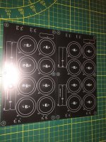
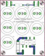
Boards for 7x 25mm snap-in caps
I ordered these by mistake, i meant to order the version with 4 electrolytics.
These are suitable for a wide range of voltages, and will accept most 25mm diameter snap-in electrolytics.
Color is green, asking €2.50 each add a quarter each for the fuse holder.
Edit, my phone is dead so i cannot make photo's of the boards themselves now