I am thinking of building a speaker with a front loaded horn made of acoustic foam.
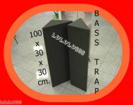
I am going to use the corner bass traps in the picture which I already have. They are 30cm wide and 30cm deep.
IDEA 1
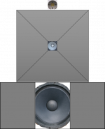
is to put a 15" woofer in the horn ( I have GPA 416s). Woofer can be open back or in sealed cabinet.
Crossed over to a BG Neo8s at 800hz.
Neo8s hanging freely inside horn mouth at ear level (see pic).
Basicly a two way (subwoofer can be added) with Neo8s doing upper mid and treble. I will tweak Neo8s with foam/felt to increase vertical dispersion; no worries in that department. And the drivers can be time-aligned on miniDSP; no worries there either.
What do you think overall about IDEA 1?
I am going to use the corner bass traps in the picture which I already have. They are 30cm wide and 30cm deep.
IDEA 1
is to put a 15" woofer in the horn ( I have GPA 416s). Woofer can be open back or in sealed cabinet.
Crossed over to a BG Neo8s at 800hz.
Neo8s hanging freely inside horn mouth at ear level (see pic).
Basicly a two way (subwoofer can be added) with Neo8s doing upper mid and treble. I will tweak Neo8s with foam/felt to increase vertical dispersion; no worries in that department. And the drivers can be time-aligned on miniDSP; no worries there either.
What do you think overall about IDEA 1?
Attachments

Member XRK971 has done a lot of work with foam horns with good result, you might want to look at some of his stuff, or drop him a PM.
he has been working with foam-core board which is a completely different material.
mine is open-cell acoustic foam which is a sound absorbing material.
the idea here is to reduce diffraction and resonance, but still be able to air-load the driver.
thanks.
mine is open-cell acoustic foam which is a sound absorbing material.
the idea here is to reduce diffraction and resonance, but still be able to air-load the driver.
thanks.
Go for it.
Freddyi has some neat pics from frazier (horns and foams).
To me, foam or felt won't do much below 2khz.
I dont think foam can help vertical dispersion.
Freddyi has some neat pics from frazier (horns and foams).
To me, foam or felt won't do much below 2khz.
I dont think foam can help vertical dispersion.
Its a cool idea. Points for thinking outside the box.
I anticipate it will have very little practical effect, depending on the density of the foam.
It also may be frequency dependent. If you decide to try it, please report back.
I for one would be interested in your experiences.
I anticipate it will have very little practical effect, depending on the density of the foam.
It also may be frequency dependent. If you decide to try it, please report back.
I for one would be interested in your experiences.
I think you'll get too much cancellation with it open backed because the foam will have very little effect at that frequency.What do you think overall about IDEA 1?
I want to hear IDEA 2 now
Go for it.
Freddyi has some neat pics from frazier (horns and foams).
To me, foam or felt won't do much below 2khz.
I dont think foam can help vertical dispersion.
Forum member OllBoll have shown that a 50cm wide baffle made of a layer of wool carpet underlay smoothed the baffle peak and lowered the -3db point down to 200hz. The thread is my personal favorite in this forum:
Dipole wool carpet baffle experiment
So I am guessing that the 90cm wide and 30cm deep bass traps can help the woofers down to at least 100hz in the OB scenario.
Even if the absorption/F-B seperation is not good enough, the air-loading the cone function should still work, which would increase the qts and LF extension.
Regarding the vertical dispersion: please read these
Opzetje dipool Neo8 & 2x Seas L21RNX/P + cornerwoofers - Pagina 2 - forum.zelfbouwaudio.nl
www.audioexcite.com >> RAAL 140-15D
Last edited:
I think you'll get too much cancellation with it open backed because the foam will have very little effect at that frequency.
I want to hear IDEA 2 now
IDEA 2 coming up once we finish discussing IDEA 1😉
Horn mouth termination is important
Perhaps the most important issue is the termination of the horn mouth. If the horn mouth ends abruptly, an acoustic wave (resonance) is created which reflects back into the horn throat. The way to avoid this is by putting a large radius at the horn mouth.
A round 180 degree roundover is the essential difference between the LeCleach horn profile and a tractrix.
Retsel
well, the idea of an absorbant horn is to address the problems of resonance and diffraction we observe with non-absorbant horns.
i think ollboll's experiment with an absorbant baffle is perfectly relevant.
a sharp baffle edge cause diffraction (rounding-over is used to mitigate this effect too).... however the ripples disappear when an absorbant baffle is used...and all the benefits of a baffle are still there!
i am expecting the same with an absorbant horn.
Idea 1
My first comment is that the horn that you are proposing will not load the driver to 100 hz. However, if all you are trying to do is create a different style baffle which lowers the cancellation frequency, then this could work. This style of baffle will avoid resonances caused by parallel wings.
I agree with what someone else has said, which is that the rear wave is more important than the front wave and that you will still have dipole rolloff probably at a higher frequency than what you think. One way to fix this is to create a horn like baffle for the rear of the driver. This will do a lot more to reduce cancellation, and it will load the back of the driver the same as the front of the driver.
One concern I would have is that horns improve the dynamics of speakers, and the foam will dampen the dynamics, so you might gain some benefits at the baffle edge, but loose midbass dynamics (this is why back horn or tapped speakers have little adsorbent material in them). So, while the wool baffle experiment worked well for a flat baffle, it may not work so well for a horn-style baffle where the pressures are higher.
Perhaps another thing to think about or try is to use a hard material for the baffle nearest to the speaker and then a softer material closer to the mouth of your horn/baffle. The classic example of this is speaking into a conical horn. The person who demonstrated this spoke into the conical horn with an abrupt termination, and then wrapped some sort of cloth material at the mouth of horn. Apparently, the improvement in intelligibility was impressive.
If you are looking for a flexible way to try different horn curves / sizes use "wiggle" board ---known as bendable plywood in the U.S.A. This material is easy to work with and can be coated with epoxy to keep a permanent shape. Multiple layers can be added for mid bass horn duty along with wood braces if more rigidity is required.
a soft baffle extends the LF extension as much as a hard baffle and has the added advantage of reduced baffle/dipole peak and ripples afterwards...
a soft horn would likely have all the pros of a soft baffle aaaaand also increase the qts of the driver...
but i did not want this to be an open baffle discussion; as I have said, the woofer could be sealed too. (or even bass reflex; imagine altec 825 cabinet)
a soft horn would likely have all the pros of a soft baffle aaaaand also increase the qts of the driver...
but i did not want this to be an open baffle discussion; as I have said, the woofer could be sealed too. (or even bass reflex; imagine altec 825 cabinet)
Resonances in Horns
First of all, I am interested in this topic because I will begin to try out some front horns for my Lowthers.
Lynn Olson discussed the issues of horn resonances in a piece that he posted online which can be found here:
The Art of Speaker Design
Here is the excerpt in that piece that discusses resonances. Particularly look at the part talking about the issues when the horn is too short.
The flip side of this coin is the fact that the most articulate horn/triode advocates have already owned, and discarded, mainstream audiophile systems. As a fairly mainstream speaker designer myself, I can attest that raising the efficiency of conventional direct-radiators is most certainly worthwhile ... you get a significant improvement in clarity, immediacy, and naturalness, and your choice of amplifier opens up to much more interesting technologies.
From a technical standpoint, horn-loaded drivers typically have very low THD, IM, and FM distortion, uneven frequency response, reflections in the time domain, and very sharp cutoff characteristics at both ends of the frequency range. From the viewpoint of mainstream high-end designers, horns are beset by serious problems with impulse response, diffraction, and smooth dispersion.
The root of these problems, especially with cheaper PA-style horns, is the acoustic reflection from the edge of the horn-mouth. When a sound wave moves across a sharp boundary, it diffracts and re-radiates in all directions, like a separate driver located at the point of the reflection. The reflected wave from the horn-mouth then bounces back into the throat, which typically has a hard phase plug or a driver with a stiff cone. After it strikes that, it reflects right back outward again ... this succession of reflections is called a series reflection, and it is far more audible than the small ripples in the frequency response might indicate.
Although the frequency response doesn’t really indicate the full impact of the reflections, they show up in the impulse response or 3D waterfall display. (This is most clearly seen if the horn driver is measured without a crossover.) Inexpensive PA horns that are too short suffer most severely from this problem, and have the grossest "horn coloration" as a result.
There are solutions for this problem that work pretty well. If you can afford to lose 1 or 2dB or efficiency, you can line the inside of the horn with 1/8" wool felt. 1 to 3 inches extending from the lip of the mouth going inward will do the trick. The further you go back towards the throat, the better the damping, but if you overdo it, the bass response of the horn will start to droop, along with the efficiency. Think of it being like tweaking the VTA on your cartridge and you’ll be heading in the right direction. Of course, if you have access to a MLSSA or similar FFT system, you can adjust the impulse response to taste, as well as compensate the crossover accordingly. (Note: if you’re modifying a commercial horn, don’t forget to remove the wire mesh bug screen in the throat. The wire mesh creates a very unpleasant gritty harshness at levels above 90dB, and is only required for severe outdoor environments.)
The best solution is to eliminate the mouth reflection entirely. This has already been done with the Tractrix horn profile, invented by P.G.A.H. Voight in the late Twenties!
The Tractrix still has a sharp edge at the horn mouth, but the horn wall has already curved through 90 degrees before the sound hits the boundary. The reflected sound then has the difficult task of curving back through that 90 degree curve before it can strike the phase plug. Therefore ... no standing wave, only one modest reflection, and very little of the "horn sound" if the compression driver is correctly designed.
(Note: there are rectangular horns on the market that are Tractrix-profile in only one dimension; since the reflection is still an unresolved problem on two of the mouth edges, most of the benefit of the Tractrix profile is lost.)
Building a square or circular mouth Tractrix horn is no simple exercise, and I defer to "Speaker Builder" and "Sound Practices" magazines for the complex procedure on how to make these things. If you’re getting the impression that doing justice to horns is a complex and expensive exercise, you’re absolutely right.
For example, the best 2" compression drivers for a 500Hz to 22kHz horn are made by JBL and TAD for studio-monitor use, and they cost $800 each, not including the horn! Compare that to a top-of-the-line Scan-Speak driver at $120, and the difference in parts cost becomes obvious. Yes, you can get entry-level PA horns for about $80, but you really get what you pay for in the prosound business. Don’t expect a grunge-band PA driver to sound like a JBL 2" titanium-diaphragm studio-monitor driver. They may look the same on the outside, but they’re not the same on the inside.
With horns, the difference in quality between the best and "bad" is really large, and much more obvious than the differences between audiophile speakers. Not only that, the best ones are seriously expensive, requiring machined Alnico magnets, diaphragms made from exotic metals, and horns with compound curves made to exacting dimensional tolerances. It’s not a technology that lends itself to cost reduction. On the bottom end of the market, we get low-grade PA speakers, which require a lot of careful modification before than can get anywhere near the "high fidelity" appellation.
Here is a patent for a horn which attempts to address resonances/reflections
Sound reproducing device
US 1840992 A
ABSTRACT available in
IMAGES(1)
Patent Drawing
CLAIMS available in
DESCRIPTION (OCR text may contain errors)
T. WElTLlNG `lan. 12,' 1932.
SOUND REPRODUG I NG DEVI GE Filed Nov Patented Jan. 12, 1932 PATENT OFFICE;
TEBIJON' WEITLING, 0F NEW YORK, Y.
SOUND BEPRODUGING DEVICE 'Appudatmn mea november 27, 1929. seriai 110,410,036.
This invention relates to a sound reproducing device adapted ,to be used in connection with radios, phonographs, talking motion pictures, piano and organ construction or in any other similarl art wherein a sound reproducing or transmitting meansis used and in which a structure of the character hereinafter described is capable of use.
The invention resides in the structure of ahorn, tone chamber, ba'lle board or similar means used as part of a sound reproducing device. It is well known that when a horn or cone is used as part of a loud speaker,
such a horn or cone usually consists of a conical imperforate member and possesses distinct directional characteristics. f That is to say, a horn or cone when used as Valoud speaker acts to ldistribute sound merely in the direction in which the mouth of the horn faces. Incidentally, many horns or other y sound chambersused in loud speakers possess undesirable resonance which acts greatly to y impair the tone quality of the source of sound,
v whether it be radio, phonograph or the like. The object, therefore, of my invention is to provide a horn, tone chamber, baffle board Vor other element in which the undesirable directional characteristics of the ordinary horn, cone or tone chamber will be avoided;
,. which will act to distribute sound in lall directions within the room in which the device is located, and'nally, which will by reason of its construction avoid the resonant characteristics found in many reproducing devices which greatly impair the true reproducing ability of such devices.
In the followingl description, I showl an illustrative embodiment ofimy invention as applied to a horn or similar sound reproduc- 40 .ing device. I do not attempt to illustrate in the drawings the various uses to which the broad idea may be put,'since to do so would result in a needless multiplicity of illustrations. It will be understood however, that when refer to a"horn inwhich I utilize the principle of my invention I may well mean 4 the whole or part of a tone chamber or casing, aportion of a cone-shaped orfdisk loud speaker,y a part of a phonograph, piano or organ or other musical instrument, or a baffle board construction or casing as used in connection with certain types of speakers of the type widely in use at the present time.
Reference is to be had tothe accompanying drawings, forming aA part hereof 1n which Y Figure 1 is a longitudinal `sectional view of an illustrative form of horn made in accordance with my invention;
Figure 2 is a transverse sectional view of the same near theopening or mouth of the horn on the line 2-2 of Figure l, looking in the direction of the arrows;
Figures 3 and 4 are longitudinal sectional views of several of the many modifications of my improved structure;
Figure 5 lis a sectional view in enlarged form illustrating the manner in which a form of horn may be made;
Figure 6 is a sectional view on the line 6--6 of Figure 4 looking in the direction of the arrows, and
Figure 7 is a sectional view showing a modified way of making a cone, horn or any portion of a sound chamber.
` Throughout the various views of the drawings, similar reference characters designate similar parts.
In the illustrative embodiment of my invention disclosed in Figures 1 and 2 of the drawings, ll indicates the'body of a sound reproducing device, which I have 'shown in simple horn form. As heretofore pointed out however, the structure lmay well be a casing for a ,speaker or a wall or wall section orl series of such sections for any other type of sound reproducing device: The simple conical type of horn shown is provided with the vusual bell or mouth 2 and contracted opposite end 3 which receives the reproducing unit 4. In carrying out my invention, the horn is made of a body 5 which may be made of any suitable material of sufiicient stiffness to maintain the horn in its proper shape. I contemplate the use of thin perforate metal, papieranche, wire mesh, wood, wicker, bamboo, o-r any other material suitable for the purpose. The stiff material 5 forming the body of the horn is preferably provided throughout its entire surface with a series of perforations G. Any foraminous material such as a skeleton frame work of strip material with spaces between will suilice. These perforations can be very closely spaced; they may vary in shape and-size; they `may be situated in various areas of the horn and they may be in the form of slits, slots or various shaped openings. These perforations may be placed throughout the area of the horn or they may be localized to suit different requirements of sound distribution. It is also entirely feasible to use one or more large openings in place of a series of small openings, if desired.
To dampen out undesirable resonance in the horn, I find it desirable to line both inner and outer faces of the horn with a suitable sound dampening material such as indicated at 7 and 8. This material may be in the form of loosely compacted felt, bui-lap, carpet, plush, felt, sponge rubber or 'some other material of similar characteristics placed on in single or multiple thickness. It is not perforated but is preferably of open characteristics to the extent of permitting penetrability of the sound.
Through the structure just described, it Will be seen that by the provision of openings in the side Walls of a sound reproducing device, the directional characteristics of snch device are dissipated. There isa tendency for the sound to extend laterally through the openings and dampening covering, the amount of such lateral disposition of the sound being dependent upon the size and shape of such openings and upon the location of the same, together with the'thickness and density of the fabric covering.
It is true that by the utilization of such a structure that I have just described, the volume is slightly decreased. This is however, relatively unimportant since most radio sets, microphones, phonographs and other sound reproducing devices are to-day operated with more power than actually needed. This loss of power is amply compensated for in my device by distinct gain in clarity and naturalness of tone, with reserve volume to hold vunder control.
In Figure 3 a horn is shown in which perforations 2O are.. provided throughout the .area of the inner stiifening layer, and only a portion of the horn is covered by the dampening layer 22.
In Figure 4, I have illustrated an embodi ment of my invention wherein a horn-shaped member 9 is disclosed, the same being built up of a substantially rigid body 5 and resonance dampening outer and inner layers 7 and 8, similar to those described with respcct to Figure l. The shape of the horn employed however, differs from that disclosed in Figure l since I provide it with transverse partitions l0 and Il, the inner layer of these partitions being provided with a plurality of perforations 12 and 13 and these partitions being' covered by imperforate dampening fabric on one or both of their faces. Additionally, I provide the horn 9 with a surrounding concentric enclosure member I4, the supporting inner layer of which may be Vperforated as at l5, and also covered with resonance-dampening fabric on one or both of its faces.
The structures illustrated in Figures 3 and Li are several of many forms that may be employed to cause the sound waves reproduced topass through a devious course before actual exit into the room. A dampening tendency and a dissipation of resonance is thereby secured.
I have herein described several embodiments of my invention which is capable of many modifications. The perforated principle, combined with the utilization of resonance dainpening means may be applied to any type of tone chamber. If desired, a horn may beprovided with a series of perforated and dampened baille plates, a suggestion of which is contained in Figure Li. These and many other modifications may be made in my invention, without departing from its spirit.
I-Iaving described my invention, what I claim is:
l. In a sound-reproducing device, a soundreproducing unit and a sound-amplifying wall structure directly associated therewith, said structure having a wall portion provided with openings, and a sound-dampening element consisting of a soft, penetrable substance extending over said Wall portion and covering the openings therein.
2. A sound-reproducer having a sound-reproducing unit, an amplifying wall structure connected to said unit and directly associated therewith for ,so-und reproduction, said structure having a wall portion provided with openings in it, one face of said wall portion and the openings therein being covered by a soft, penetrable sound-da1npening element.
3. A soundaeproducer having a sound `chamber provided with a wall in the form 'of a perforated element, the face of said elea sheet of soft, permeable sound-dampening fabric covering the wall and the perforations therein.
5. A sound-reproducer having a sound chamber provided with a Vperforated wall structure, a part of which 1s covered by a soft, resonance-dampening textile fabric.
6. A sound reproducer having a sound chamber provided with a. perforated wall layer and a. soft, penetrable dampening material disposed on opposite faces of said wall.
Signed at the oit of New York, county of New York, and tate of New York, this 26th day of November, 1929.
TERIJON WEITLING.
REFERENCED BY
Citing Patent Filing date Publication date Applicant Title
US3027964 * 24 Jun 1958 3 Apr 1962 Ampex Loudspeaker
US3174578 * 27 Sep 1962 23 Mar 1965 Seiichi Kojima Contracted horns with least mouth reflection and some wall leakage
US4706295 * 28 Oct 1980 10 Nov 1987 United Recording Electronic Industries Coaxial loudspeaker system
US5115883 * 7 Sep 1990 26 May 1992 Pioneer Electronic Corporation Loudspeaker
US8953831 28 Sep 2012 10 Feb 2015 Bose Corporation Narrow mouth horn loudspeaker
US9451355 31 Mar 2015 20 Sep 2016 Bose Corporation Directional acoustic device
US9538282 * 29 Dec 2014 3 Jan 2017 Robert Bosch Gmbh Acoustically transparent waveguide
US9762994 * 2 Dec 2016 12 Sep 2017 AcoustiX VR Inc. Active acoustic meta material loudspeaker system and the process to make the same
US20170085981 * 2 Dec 2016 23 Mar 2017 AcoustiX VR Inc. Active Acoustic Meta Material Loudspeaker System and the Process to Make the Same
* Cited by examiner
CLASSIFICATIONS
U.S. Classification 181/184, 181/180
International Classification H04R1/32, H04R1/34
Cooperative Classification H04R1/345
European Classification H04R1/34C
Blog post discussing horn honk caused by abrupt termination at the mouth
See:
Factors Affecting Sonic Quality of Mid & HF Horns & Waveguides
See:
Factors Affecting Sonic Quality of Mid & HF Horns & Waveguides
my soft front-horn/waveguide is for under 800hz
any hard baffle or horn helps the low end but also introduces a peak....
absorbent baffle/horn could be good for both ends
any hard baffle or horn helps the low end but also introduces a peak....
absorbent baffle/horn could be good for both ends
I am thinking of building a speaker with a front loaded horn made of acoustic foam.
I've posted similar re extending/shaping the response of 500 Hz-up horns using both acoustic fiberglass insulation [earlier versions of OC 703] and dense open cell foam camping mattress [AKA 'Trail pad' back then] when appropriate and continue to recommend it for any horn that doesn't have a proper end correction flare to somewhat mimic one, so see no reason why it can't be successfully done on a woofer, but it will need to be quite large/dense to go low IME.
Never tried it, but maybe a pegboard backer baffle with foam on both sides? PegBoard Systems, Metal PegBoard, Hardboard, Mounting, Hooks, Baskets
Re for dipole, as already noted, a front, rear baffle is required IME and may need to fill in the gap as required to fine tune it. Worked a treat when I coupled two cheap 8" 'full-range' drivers magnet to magnet [bipole] for an interesting sounding mono TV 'upgrade'.
GM
Last edited:
- Status
- Not open for further replies.
- Home
- Loudspeakers
- Multi-Way
- Front loaded foam horn ideas