Hi all,
I am using a NABU case from Nebraska Surplus to build another Pass B1 buffer. This will be my second with the NABU case, which comes with an 18v power supply.
Alas, the units date to the mid-1980s. The caps physically look good, but given their age and ease of replacement, it seems like a good idea to replace them.
The main filter cap is a Rubycon CE 69 W (22,000uf, 16v), which is listed as a snap-in capacitor.

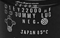
The confusing part is that the cap has four lugs. One is clearly a dummy, two are clearly active, and one is?
The cap has a diameter of 40mm and the live lugs are not centered, but toward one side.
(Picture is not mine, but the cap illustrated is the same series):

The lug on the left-hand side (9:00 o'clock) is definitely a dummy used for support purposes.
My question is if I would I order a 3-lug replacement?
Thanks for any help you can give me!
I am using a NABU case from Nebraska Surplus to build another Pass B1 buffer. This will be my second with the NABU case, which comes with an 18v power supply.
Alas, the units date to the mid-1980s. The caps physically look good, but given their age and ease of replacement, it seems like a good idea to replace them.
The main filter cap is a Rubycon CE 69 W (22,000uf, 16v), which is listed as a snap-in capacitor.

The confusing part is that the cap has four lugs. One is clearly a dummy, two are clearly active, and one is?
The cap has a diameter of 40mm and the live lugs are not centered, but toward one side.
(Picture is not mine, but the cap illustrated is the same series):

The lug on the left-hand side (9:00 o'clock) is definitely a dummy used for support purposes.
My question is if I would I order a 3-lug replacement?
Thanks for any help you can give me!
I can see a bit of the "crosshatched/scored " face of the lug as nearest the NEGATIVE marking on the capacitor , that ---at least to me --signifies that that one is the "negative " lug otherwise it goes against world industrial convention .
I have never come across a negative and positive lug so near each other so from my point of view the one in the middle is a support lug and the two lugs on either side of it are one positive and the other "negative " /earth.
Easy to check with an ohmmeter to see if there is any connection to the ones on either side.
The sleeve mark for negative too is near the single lug...
Odd one, that.
Take a look at the circuit...
The only ones I have seen with many connections are the big ones used with refrigerator and air conditioning compressors, one common and one each for start and run windings.
Sometimes it is a double lug, so you can run two pairs of wires.
That is three connectors, but four is a new one for me.
Last edited:
It should be possible to reverse-engineer it by looking at the PCB traces, or to look it up in the capacitor datasheet.
Lately I have used some supercapacitors that came in a very similar package. For those, the pin on the left was negative, the central pin on the right positive and the two around it were for mechanical support.
By the way, when you connect a fully discharged large electrolytic capacitor to a multimeter set to a high resistance range, the time it takes the resistance read-out to go from 0 to out of range is roughly proportional to the capacitance. You can use that to check whether the pins are actually connected to a big capacitor.
- Home
- Design & Build
- Parts
- Four lug capacitor replacement
