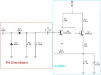
Yes, It is AM demodulator but i found also that is FM demodulator too.
http://www.zen22142.zen.co.uk/Theory/diode_pump/diode_pump.htm
(end of this document)
My professor said that is true and i need to find how this thing work... 🙁
http://www.zen22142.zen.co.uk/Theory/diode_pump/diode_pump.htm
(end of this document)
My professor said that is true and i need to find how this thing work... 🙁
You've answered your own question - it is a form of charge pump F to V converter.
F to V converter = FM demodulator.
F to V converter = FM demodulator.
....It's kind of an interesting take on FM demod. I'm wondering why it hasn't been widely used before? ...Maybe it has? Cheaper than transformers. Maybe distortion performance is poor?
To make it work properly in FM you have to carefully control the input pulse height so as to get rid of the AM demodulation.
If you read the analysis posted above you will see that it is about 100 times more sensitive to AM than to FM, so its noise performance will be very poor.
If you read the analysis posted above you will see that it is about 100 times more sensitive to AM than to FM, so its noise performance will be very poor.
Just a thought - if you put the input through a limiter and then ran a dual differential diode charge pump (reversing the diodes in the second pump) you should be able to reduce the AM demodulation significantly.
Any AM which escapes the limiter could be made to excite both demodulators equally and so be eliminated if the differential stage has good CMRR. The trick would be to make one of the integrating resistors on the charge pumps variable as this is the major determinant of Vout/ Fin so it needs to be able to tune out the difference in the integrating capacitors.
Any AM which escapes the limiter could be made to excite both demodulators equally and so be eliminated if the differential stage has good CMRR. The trick would be to make one of the integrating resistors on the charge pumps variable as this is the major determinant of Vout/ Fin so it needs to be able to tune out the difference in the integrating capacitors.
Hi Mark Kelly
This is an interesting idea. Is it possible to sketch a circuit on this?
Regards
George
This is an interesting idea. Is it possible to sketch a circuit on this?
Regards
George
gpapag said:Is it possible to sketch a circuit on this?
Just take the circuit diagram as abiove and duplicate it. In the second one, reverse diodes d1 and d2 and replace R1 with a 2k variable. Add your own diff amp and you are set.
- Status
- Not open for further replies.
- Home
- Source & Line
- Analog Line Level
- FM Demodulator