Hi everyone,
I'm hoping someone can shed some light on my situation (probably fairly obsolete these days)
Quick rundown of the parts:
Ford E250 camper
- has "common ground" speaker wiring. Only one ground is shared between all speaker positives.
Alpine UTE-BT73 head unit
- has "floating ground", aka modern +/- speaker wire outputs.
Scosche FGA floating ground adapter
- takes in 8 modern +/- speaker input (and a "ground" reference connected to headunit chassis) and outputs to the old school common ground system (4 speaker +, and one ground).
Alpine KTP-445A amp
-supposed to be plug and play with Alpine head units
-takes as input the entire harness from the head unit
-outputs the entire headunit harness as if it was coming straight out of the headunit, with a higher amplified signal on the "speaker-level" wires
---------------------------------------------------------------------------------------
Working setup without amp (1):
Headunit -> FGA -> car harness -> speakers
This is working great. Balance/fader works, all speakers are equally loud. If you disconnect the ground input for the FGA (connected to headunit chassis), then the audio gets a lot quieter.
Now, I am trying to add a KTP-445A mini amp to the setup.
Theoretical setup with amp in a modern vehicle:
Headunit -> KTP-445A -> car harness -> speakers
Non-working setup with amp and FGA (2):
Headunit -> KTP-445A -> FGA-> car harness -> speakers
This is not working properly. With the FGA still grounded to the headunit like it is in setup 1, there is almost no signal going to the FR and RL speakers. Most of the sound is going to FL and RR. If you disconnect the FGA's input ground, then there is seemingly equal audio signal going to all 4 speakers, but the fade and balance don't work properly (you can't isolate the audio signal to any one speaker). For example, if I set the the fader/balance all to FR, there is basically no sound at all. This also happens with the FGA input connected.
I have tried connecting the FGA's input ground to car ground, or to the amp chassis, instead of the headunit chassis, but the exact same thing happens. I suppose I could leave it as is with the FGA's input ground NOT connected since I don't really need fader/balance, but I'm afraid this could cause damage, or not be getting full power.
Side note: The Scosche FGA is very simple and only has some capacitors inside it. I initially had a different FGA: Peripheral FGA4. It had some extra parts in it (transformers?) and would actually produce heat! The Peripheral FGA worked just fine without the amp, but would not output sound at all with its input ground disconnected. With the amp, it would get quite hot with the input ground disconnected (and same non-working fader/balance), and with the input ground connected had the same problem with the sound going mainly to the FL and RR. I like the new Scosche one since it doesn't produce heat and waste energy. But I included this info as it could provide some clues.
I am trying to understand what's going on but it's difficult without understanding what a floating ground adapter does internally. @oPossum , it looks like you have some experience with these floating ground adapters as I saw in a different thread.
Can anyone shed some light on how a floating ground adapter works electrically and what it's supposed to do? Why isn't fader/balance working anymore? Why does sound go mainly to two channels when I connect the FGA's input ground like it's supposed to be? Where should I ground the FGA now that the amp is in the picture?
I'm hoping someone can shed some light on my situation (probably fairly obsolete these days)
Quick rundown of the parts:
Ford E250 camper
- has "common ground" speaker wiring. Only one ground is shared between all speaker positives.
Alpine UTE-BT73 head unit
- has "floating ground", aka modern +/- speaker wire outputs.
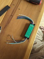
Scosche FGA floating ground adapter
- takes in 8 modern +/- speaker input (and a "ground" reference connected to headunit chassis) and outputs to the old school common ground system (4 speaker +, and one ground).
Alpine KTP-445A amp
-supposed to be plug and play with Alpine head units
-takes as input the entire harness from the head unit
-outputs the entire headunit harness as if it was coming straight out of the headunit, with a higher amplified signal on the "speaker-level" wires
---------------------------------------------------------------------------------------
Working setup without amp (1):
Headunit -> FGA -> car harness -> speakers
This is working great. Balance/fader works, all speakers are equally loud. If you disconnect the ground input for the FGA (connected to headunit chassis), then the audio gets a lot quieter.
Now, I am trying to add a KTP-445A mini amp to the setup.
Theoretical setup with amp in a modern vehicle:
Headunit -> KTP-445A -> car harness -> speakers
Non-working setup with amp and FGA (2):
Headunit -> KTP-445A -> FGA-> car harness -> speakers
This is not working properly. With the FGA still grounded to the headunit like it is in setup 1, there is almost no signal going to the FR and RL speakers. Most of the sound is going to FL and RR. If you disconnect the FGA's input ground, then there is seemingly equal audio signal going to all 4 speakers, but the fade and balance don't work properly (you can't isolate the audio signal to any one speaker). For example, if I set the the fader/balance all to FR, there is basically no sound at all. This also happens with the FGA input connected.
I have tried connecting the FGA's input ground to car ground, or to the amp chassis, instead of the headunit chassis, but the exact same thing happens. I suppose I could leave it as is with the FGA's input ground NOT connected since I don't really need fader/balance, but I'm afraid this could cause damage, or not be getting full power.
Side note: The Scosche FGA is very simple and only has some capacitors inside it. I initially had a different FGA: Peripheral FGA4. It had some extra parts in it (transformers?) and would actually produce heat! The Peripheral FGA worked just fine without the amp, but would not output sound at all with its input ground disconnected. With the amp, it would get quite hot with the input ground disconnected (and same non-working fader/balance), and with the input ground connected had the same problem with the sound going mainly to the FL and RR. I like the new Scosche one since it doesn't produce heat and waste energy. But I included this info as it could provide some clues.
I am trying to understand what's going on but it's difficult without understanding what a floating ground adapter does internally. @oPossum , it looks like you have some experience with these floating ground adapters as I saw in a different thread.
Can anyone shed some light on how a floating ground adapter works electrically and what it's supposed to do? Why isn't fader/balance working anymore? Why does sound go mainly to two channels when I connect the FGA's input ground like it's supposed to be? Where should I ground the FGA now that the amp is in the picture?
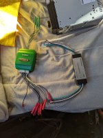
@Perry Babin , here you go!
Last pic is of both the new FGA and my old one (which was more complex). I have a multimeter but no scope.
Last pic is of both the new FGA and my old one (which was more complex). I have a multimeter but no scope.
Attachments

I'm not sure why I can't quote you. I replied above with the pictures! I have a multimeter, but no scope.
Drive a signal (that would result in a relatively high speaker output) into the alpine amp (speakers connected or not) and find the OUTput speaker wires that show signal (meter on AC volts) while the amp is playing. List those wires including noting the output polarity (positive or negative connection for speaker).
At which interface do you want me to test this? Headunit out, amp in/out, FGA in/out?
I assume I put the positive test lead on the speaker wire and the negative on chassis ground?
I assume I put the positive test lead on the speaker wire and the negative on chassis ground?

I have some bizarre results to report! This was tested with a 100Hz sine wave at a fairly high volume with the amp and speakers connected. Multimeter set to AC 200, negative lead on car's ground wire that feeds into to amp/headunit and positive lead on the various FGA outputs.
FGA outputs with FGA input ground grounded on headunit chassis:
LF: 2.4V
RF: 0.1V
LR: 0.1V
RR: 2.4V
Ground: 0.0V - 0.2V
FGA outputs with FGA input ground NOT connected:
LF: 2.0V - 3.5V
RF: 0.1V - 1.5V
LR: 0.1V - 1.5V
RR: 1.8V - 3.4V
Ground: 0.8V - 1.5V
This one is baffling. The voltages changed almost every time I un-grounded the FGA's input ground off the headunit chassis, and then stayed fairly stable. It may be related to how long it's been since I disconnected the ground as I was measuring the high voltages right after disconnecting the ground. However, the sound instantly changes when you remove the input ground: going from basically a really loud only LF and RR to lower but seemingly equal volumes on all channels. This is how I've been listening to it since installing the amp. This can't be right! Please let me know what to test next, this is exciting 🤣.
I need the voltage on the outputs of the alpine amplifier, both positive and negative speaker wires.
Ah, okay, that's why I asked last night where you'd like me to measure. Regardless, you're a genius, I think we're onto something!
KTP-445A amp outputs:
LF+: 2V
LF-: 0V
RF+: 0V
RF-: 2V
LR+ 0V
LR-: 2V
RR+: 2V
RR-: 0V
KTP-445A amp outputs:
LF+: 2V
LF-: 0V
RF+: 0V
RF-: 2V
LR+ 0V
LR-: 2V
RR+: 2V
RR-: 0V
There's the problem. The amp is set up like a bridgeable amp where half of the signals are on the negative speaker wires.
Are you running this in a car (E250) where the speakers (OEM?) have one terminal directly connected to the chassis of the vehicle?
Are you running this in a car (E250) where the speakers (OEM?) have one terminal directly connected to the chassis of the vehicle?
Why would the amp do that? Indeed, the universal version of this amp (KTP-445U) is "bridgeable", although I'm not sure what that means. I thought it meant bridging 2 channels into 1 so you get double the power on only 2 channels instead of 4.
Yes, running in the E250. Speakers have been upgraded, but the stock common ground wiring setup has not been. So yes, I believe that each speaker connects to the chassis of the vehicle, although I haven't visually confirmed that. According to the wiring diagrams, it's on a common ground system for all speakers.
Yes, running in the E250. Speakers have been upgraded, but the stock common ground wiring setup has not been. So yes, I believe that each speaker connects to the chassis of the vehicle, although I haven't visually confirmed that. According to the wiring diagrams, it's on a common ground system for all speakers.
Is running dedicated speaker wires out of the question?
Check the speaker locations to see what the ground is for each speaker.
Check the speaker locations to see what the ground is for each speaker.
The speaker wires go from the speakers to a connector and then up into a harness and into the body so I'm not sure where they go. But this is the whole reason why I had to use a FGA, which works perfectly as intended without the amp!
Yea I'd really really like to avoid running new wires. Getting to the very rear speaker will be really tough. I suppose I can't just swap the +/- wires that have signal can I? Is there anything I can do to the amp internally? It's quite easy to open up. Or what about the FGA?
Yea I'd really really like to avoid running new wires. Getting to the very rear speaker will be really tough. I suppose I can't just swap the +/- wires that have signal can I? Is there anything I can do to the amp internally? It's quite easy to open up. Or what about the FGA?
Last edited:
Some of the old speakers had the ground terminal connected to the speaker frame so it made the ground connection when the speaker was bolted into place.
If you have a short length of two wires you can connect the output of the FGA (which could be replaced with capacitors) to the negative terminal of the speaker for the amp channels that have signal on the negative terminals. For those channels, you'd reverse the positive/negative input to the FGA. That should give you what you need.
Before you do that, make sure that ALL inputs to the FGA are isolated from ALL other wires (in and out) of the FGA.
What are the values of the capacitors in the FGA?
Sweet, so there's a way! Thank you so much!
What do you mean by "to the negative terminal of the speaker"?
What do you mean by make sure that all inputs to the FGA are isolated from all other wires? Why wouldn't they be?
I will open up the FGA and let you know about the capacitors after I fuel up, I can barely think 🤔.
What do you mean by "to the negative terminal of the speaker"?
What do you mean by make sure that all inputs to the FGA are isolated from all other wires? Why wouldn't they be?
I will open up the FGA and let you know about the capacitors after I fuel up, I can barely think 🤔.
Two speakers will be wired out of phase.
I don't want to risk damaging the amplifier so I want to make sure that nothing in the FGA is connected (other than through the capacitors).
A photo of the side of the FGA board where there are traces would be helpful.
I don't want to risk damaging the amplifier so I want to make sure that nothing in the FGA is connected (other than through the capacitors).
A photo of the side of the FGA board where there are traces would be helpful.
Oh, did you mean to basically swap the +/- on the speaker wires where they connect to the speaker? That's easy to do as I can swap out the pins on the connector that connects to the vehicle harness. And then feed the FGA the negative where it expects a positive for the 2 channels that have signal on the negative wire?
I'm confused on how this amp would have worked in a modern car that doesn't need an FGA. If the signal is on the negative wire for 2 of the channels, wouldn't those speakers be out of phase compared to the normal 2?
I'm confused on how this amp would have worked in a modern car that doesn't need an FGA. If the signal is on the negative wire for 2 of the channels, wouldn't those speakers be out of phase compared to the normal 2?
Yes.
The speakers wired with standard wires would have worked just like any bridgeable amplifier when not bridged. Bridgeable amps have one of the two bridgeable channels inverted.
Do you have any DC voltage on any of the output speaker wires on the amp? If not, you may not need to FGA.
Do all of the speaker wires on the output of the amplifier that had NO signal read 0 ohms to each other?
- Home
- General Interest
- Car Audio
- Floating ground adapter not working in combination with KTP-445A mini amp