Was chatting to Joe Rasmussen tonight. He of the flat impedance ideas that some people found too difficult here. I'm with Joe on Flat impedance as a GOOD THING. I mean, we really ought to give our amps an easy load.
So I'm sharing some ideas I find interesting.
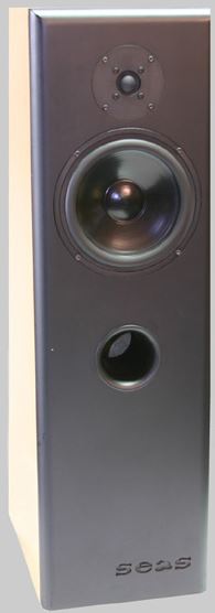
This is the sort of speaker I am modelling here, the Old SEAS Njord 8"/1" idea:
It's more fun than a carload of monkeys, IMO. I build stuff like this.
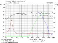
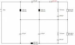
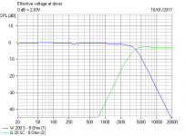
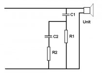
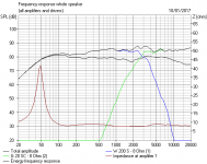
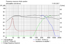
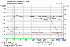
So my current bit of fun is the first parallel crossover below. I have just got a bell shaped impedance curve and added an LCR to correct impedance. The first three images on flat baffle.
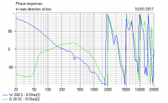
Then I remembered a Jeff Bagby idea about series crossovers in the magic 3:1 ratio with carefully calculated values. And it also looks good. I time-aligned it, but not compulsory. Usual BW3 18db/octave slopes and the 3dB FR hump at crossover.
But here's the thing. Flattish frequency response and phase alignment is always our design goal. But flattish power response and dispersion and flattish impedance is also going to help. And it really looks like you can have most of them. 😎
So I'm sharing some ideas I find interesting.
This is the sort of speaker I am modelling here, the Old SEAS Njord 8"/1" idea:
It's more fun than a carload of monkeys, IMO. I build stuff like this.
So my current bit of fun is the first parallel crossover below. I have just got a bell shaped impedance curve and added an LCR to correct impedance. The first three images on flat baffle.
Then I remembered a Jeff Bagby idea about series crossovers in the magic 3:1 ratio with carefully calculated values. And it also looks good. I time-aligned it, but not compulsory. Usual BW3 18db/octave slopes and the 3dB FR hump at crossover.
But here's the thing. Flattish frequency response and phase alignment is always our design goal. But flattish power response and dispersion and flattish impedance is also going to help. And it really looks like you can have most of them. 😎
Attachments
-
 Flat Impedance Two Way Flatt Baffle.PNG13.7 KB · Views: 3,591
 -
 Flat Impedance Two Way Flat Baffle Phase.PNG23.8 KB · Views: 2,357
 -
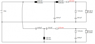
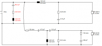 Flat Impedance Two Way Circuit.PNG9 KB · Views: 1,874
 -
 Flat Impedance Series Filter FR.PNG17.1 KB · Views: 3,972
 -
 Flat Impedance Series Filter Circuit.PNG8.8 KB · Views: 4,488
 -
 Flat Impedance Series Filter BW3 18db-octave Electrical.PNG15 KB · Views: 808
 -
 Flat Impedance Series Filter Phase Time Aligned.PNG20.1 KB · Views: 442
I had some discussion recently with someone that felt that a low output impedance was the right way to go. I feel that fixing the load is the more natural thing to do, especially with high output impedance amps. Maybe with all.we really ought to give our amps an easy load.
The problem is that the acoustical impedance gets reflected on the electrical side. I think the consumption in the resistor mainly benefits the amp.I have just got a bell shaped impedance curve and added an LCR to correct impedance.
..snip..
flattish power response and dispersion and flattish impedance is also going to help.
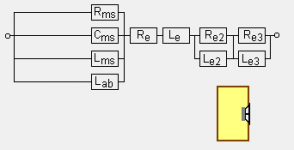
When you model a system like a loudspeaker and amplifier, you actually don't care whether its mechanical or electrical. The maths works anyway. 😎
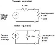
Personally, I don't think it matters whether you are using a current or a voltage amplifier either. The maths works. Norton-Thevenin equivalents.
Simulators apply an electrical model to an electro-mechanical device. A visaton woofer, for instance.
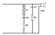
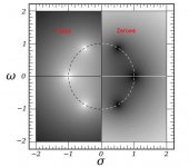
And impedance correction is a quite well established model. Two circuits from Steen Duelund. All this stuff goes back about 50 years. I'm surprised we still worry about it. 😀
Personally, I don't think it matters whether you are using a current or a voltage amplifier either. The maths works. Norton-Thevenin equivalents.
Simulators apply an electrical model to an electro-mechanical device. A visaton woofer, for instance.
And impedance correction is a quite well established model. Two circuits from Steen Duelund. All this stuff goes back about 50 years. I'm surprised we still worry about it. 😀
Attachments
Not too difficult, but too well known before.the flat impedance ideas that some people found too difficult here.
Nothing wrong with what you propose, what I found 'difficult' was one of Joe's designs that flattened the impedance hump at woofer Fs with a massive inductor... nothing wrong with that if you've got the $$$ and a suitably massive amp, but I prefer a more minimal solution (Ignore the camel in the room)
Remember that Joe is designing a speaker for anyone's amplifier. If your simpler design works with your amplifier it is better for you. Someone with a lame but 'magic' amplifier may need the extra protection(of course, if he believes that crossover parts are evil not Joe nor Steve can help him).
Putting it another way, a LR crossover gives flat response at the listening position with each driver operating at quarter power at that frequency compared to their passband. A proponent of odd order filters might appreciate flat acoustic power and response at the same time, something that could also be done using custom even order filters and might possibly use small dispersion discrepancies to advantage as well in achieving this.flattish power response and dispersion and flattish impedance is also going to help.
Not doing this can result in increased electrical impedance. The acoustic power fix will be an acoustic one. The electrical conjugate will allow the amp to see a more consistent power delivery essentially through controlled wastage.
I know what you are talking about with the -6dB crossover point in even order LR2 and LR4, Allen. These sort of filters always sound wrong to me above and below axis. The Steen Duelund graph is below.
I got interested in Power Flat when I noticed how 18dB BW3 sounded good all around the room. (And I like the hexagonal symmettry in the pole-zero maths of it.)
And PeteMck and boswald, you can tell I don't worry too much about the bass Fs correction. I don't think amps struggle with it. But valve amps have less damping, of course, so not ideal with reflex IMO, and better with closed box.
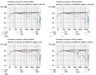
How we laugh at those noobies who go to those online calculators for designs. But actually, with Zobel impedance correction, they aren't too silly. I tried a parallel design. Below. It all works. You can even lose that +3dB FR bump by mucking up the time alignment a bit, as I do in the final dispersion plot.
Obviously, it could be flatter on FR by choosing more apt drivers, or even wallmounting, because most of the issue there is box bafflestep, but the germ of a good idea, I reckon.
I got interested in Power Flat when I noticed how 18dB BW3 sounded good all around the room. (And I like the hexagonal symmettry in the pole-zero maths of it.)
And PeteMck and boswald, you can tell I don't worry too much about the bass Fs correction. I don't think amps struggle with it. But valve amps have less damping, of course, so not ideal with reflex IMO, and better with closed box.
How we laugh at those noobies who go to those online calculators for designs. But actually, with Zobel impedance correction, they aren't too silly. I tried a parallel design. Below. It all works. You can even lose that +3dB FR bump by mucking up the time alignment a bit, as I do in the final dispersion plot.
Obviously, it could be flatter on FR by choosing more apt drivers, or even wallmounting, because most of the issue there is box bafflestep, but the germ of a good idea, I reckon.
Attachments
-
 4 S7 3rd Order Butterworth Power response off axis.PNG34.4 KB · Views: 203
 -
 3 S7 3rd Order Butterworth Time Aligned Phase.PNG27 KB · Views: 522
 -
 2 S7 3rd Order Butterworth Time Aligned.PNG22.9 KB · Views: 763
 -
 1 S7 3rd Order Butterworth 3kHz.PNG8.6 KB · Views: 564
 -
 3rdOrder_Butterworth.JPG35.1 KB · Views: 594
 -
 3rd_Order_Phase_Network.jpg86.6 KB · Views: 2,069
 -
 Aequal_root2_Steen_Duelund_filter.JPG34.6 KB · Views: 403
Last edited:
Yes. I had been doing this for about 10 years by the time I met Joe. I think it's a good cause, although with some systems there is no noticeable effect. Worth trying in case there is.Not too difficult, but too well known before.
I tend to agree with Steve. Distortion here won't be much of an issue unless it is an unexpected response peak, which won't happen with most amps.at woofer Fs
With valve amps bass damping can be controlled via the output tap, or by using this filter. All are points on a continuum.. filter or not, it is the damping that is of interest and the filter is a tool to adjust it - if required.
Obviously, I don't have to tell you guys how to simulate the bass response of a high output impedance SET valve amp in a simulator.I tend to agree with Steve. Distortion here won't be much of an issue unless it is an unexpected response peak, which won't happen with most amps.
With valve amps bass damping can be controlled via the output tap, or by using this filter. All are points on a continuum.. filter or not, it is the damping that is of interest and the filter is a tool to adjust it - if required.
How true. 😎Not too difficult, but too well known before.
But the results always interest me and AllenB, who loved that valve sound with big old Goodmans 12" bass in a big old closed box by the wall.
Closed box just goes deeper with valve or SET amps. Reflex gets distinctly flabby. 😎
Attachments
- Status
- Not open for further replies.
- Home
- Loudspeakers
- Multi-Way
- Flat Impedance and Flat Power response design.