This is my first attemp at building with tubes. The results were much better than I had hoped so its definitely not a failure to say the the least. Great sound out of this little beasty, better than any of the ss amps I've been listening to. I'm still a little iffy on working with high voltage so I shot for something simple.
I'm well aware that I'm running the 50C5's above rating but they seem happy enough, no glowing plates or grids with the lights out. All and all a fun a rewarding little project.
I'm well aware that I'm running the 50C5's above rating but they seem happy enough, no glowing plates or grids with the lights out. All and all a fun a rewarding little project.
Attachments
Looks OK to me, except for:
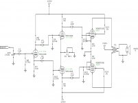
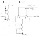
(a) lack of bias on the first stage. The 270k grid resistor R8 should not go to ground but should go to the bottom end of an extra cathode bias resistor (perhaps ~2k but that's a guess - you need to calculate it) that should be placed between the tube's cathode and the 50k cathode load resistor R7. There is no need to change the value of R7.
(b) the 2k pot R1 in the tail of the 6J6 differential amp driver. If you reduce the value of that pot too far, you'll damage the 6J6 because it will have no bias and its current will run away.
(c) the value of the driver's grid resistors R9 and R10. These seem a bit low and may place an undue load on the first stage. Increasing them to 470k and decreasing the decoupling capacitors C4 and C5 to 0.1uf might give less distortion.
(d) running in pentode mode without any negative feedback. This would cause damping to be very low (giving imprecise, woolly and boomy bass) but, hey, if it sounds good in your speaker, then OK. It would not be easy to add global negative feedback to this design but some local feedback could be added.
Tried single-ended but not enough output for my taste.
Definitley overlooked the bias issue on the input tube. Was looking at basic splitter circuits on the net to determine which I was going to use, they all seem to ommit this resistor as a way to simplify things I guess. Changing grid resistors and decoupling caps on the driver inputs seemed to make the sound less full so I swapped them back. The 2k pot is adjusted for 1.5v at the cathode (or cathodes, 6j6 datasheet shows both triodes sharing a single cathode). Was unsure about how to run the 50C5's as the only schematics I could find were the dreadful ac/dc aa5 setups, so I ran it basically how those showed it with less voltage on the screens since I'm running the plates above rating.
Definitley overlooked the bias issue on the input tube. Was looking at basic splitter circuits on the net to determine which I was going to use, they all seem to ommit this resistor as a way to simplify things I guess. Changing grid resistors and decoupling caps on the driver inputs seemed to make the sound less full so I swapped them back. The 2k pot is adjusted for 1.5v at the cathode (or cathodes, 6j6 datasheet shows both triodes sharing a single cathode). Was unsure about how to run the 50C5's as the only schematics I could find were the dreadful ac/dc aa5 setups, so I ran it basically how those showed it with less voltage on the screens since I'm running the plates above rating.
Attachments
jerluwoo said:This is my first attemp at building with tubes. The results were much better than I had hoped so its definitely not a failure to say the the least. Great sound out of this little beasty, better than any of the ss amps I've been listening to.
Amazing just how horrible those SS amps sound, isn't it?
I'm well aware that I'm running the 50C5's above rating but they seem happy enough, no glowing plates or grids with the lights out. All and all a fun a rewarding little project.
Hell yeah. That's almost the ideal way to run 50C5s (or the comparable 6.3 volt version: 6CU5) get that plate voltage up, and the screen voltage down. (Vsgsg= 90Vdc so you're close enough) and they linear up nicely. VTs are tougher than transistors, so busting the specs a bit won't do any harm.
I have a tenative 50C5 design as well, however, it looks like I'm gonna have to learn to wind my own OPT since the stock OPT for 50C5 amps SUX, and I can't seem to be able to locate a really good one.
Oh well.
Attachments
Re: Re: First tubeamp, dont laugh too hard
Hi Miles,
Contact Planet10.... he might have a few goodies for those little gems 🙂
Hi Miles,
Miles Prower said:I have a tenative 50C5 design as well, however, it looks like I'm gonna have to learn to wind my own OPT since the stock OPT for 50C5 amps SUX, and I can't seem to be able to locate a really good one.
Contact Planet10.... he might have a few goodies for those little gems 🙂
- Status
- Not open for further replies.