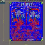
This is a small class D project targeting :
1. BTL mode, 2 x IRS2092, driven by OPA1632.
2. Using BSC320N20NS3 G 200Vds, 32mOhm, 22nC Qg
3. Output power still unknown, not going to put heatsink, trying to maximize the copper area for better dissipation.
4. Fault protection by sensing the PWM at low side gate driver.
5. Typical iraump Low/over voltage protection.
6. Reserved resistors & capacitors footprint on PCB for Post filtering feedback attempt, no idea if it works, but would like to give it a try.
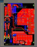
7. ACDC 100khz to 150kHz LLC
8. 24V battery backup DCDC 100khz to 150kHz LLC.
1. BTL mode, 2 x IRS2092, driven by OPA1632.
2. Using BSC320N20NS3 G 200Vds, 32mOhm, 22nC Qg
3. Output power still unknown, not going to put heatsink, trying to maximize the copper area for better dissipation.
4. Fault protection by sensing the PWM at low side gate driver.
5. Typical iraump Low/over voltage protection.
6. Reserved resistors & capacitors footprint on PCB for Post filtering feedback attempt, no idea if it works, but would like to give it a try.
7. ACDC 100khz to 150kHz LLC
8. 24V battery backup DCDC 100khz to 150kHz LLC.
Attachments
Nice 🙂  .... looking forward to hearing your results.
Be aware that BSC320N20NS3 is very fast and that it is recommended to at least make place for a gate bead.
I have tried the TO220 versions, and had massive problems with ringing ... but might just be my pour PCB design 😉
https://www.onsemi.com/pub/Collateral/AND9893-D.PDF
Massive ringing with IPP320N20N3
.... looking forward to hearing your results.Be aware that BSC320N20NS3 is very fast and that it is recommended to at least make place for a gate bead.
I have tried the TO220 versions, and had massive problems with ringing ... but might just be my pour PCB design 😉
https://www.onsemi.com/pub/Collateral/AND9893-D.PDF
Massive ringing with IPP320N20N3
Using the surface mount package and kelvin connection for the gate drive will help alot. Another trick is adding Cgs capacitance to increase dv/dt immunity for an increase in gate driver losses. Getting in to 'extreme' measures negative gate drive an be tried.
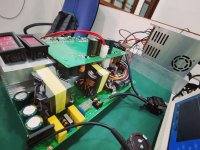
Here are some little update, just managed to powered up the ACDC(LLC) section, current sensing limited the output power to 500W. Because the smd mosfet are yet to arrive, i hook it up with to220 640 mos temporally and running them @ around 350kHz.
-Few things that I noticed are, it outputs solid stable square wave without spikes when using the correct way to measure.
-1W 5.1k VAA/VSS 5v6 zener diode resistors is running very hot, considering to change them into 3W thru hole type resistors.
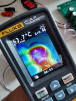
-Low Side Mos is running very warm(~70c) without heatsink, but high side mos is completely fine without heatsink during freeload. (Aliexpress Red ferrite 22uH)
-once changed to aliexpress sagami clone 22uH, the high and low side Mosfet ran very very hot (>100c) , i am wondering why.
-The output Inductors ran hot after 5 minutes, its operating at 60C and still increasing slowly, might be due to high AC voltage in the core?
-Few things that I noticed are, it outputs solid stable square wave without spikes when using the correct way to measure.
-1W 5.1k VAA/VSS 5v6 zener diode resistors is running very hot, considering to change them into 3W thru hole type resistors.
-Low Side Mos is running very warm(~70c) without heatsink, but high side mos is completely fine without heatsink during freeload. (Aliexpress Red ferrite 22uH)
-once changed to aliexpress sagami clone 22uH, the high and low side Mosfet ran very very hot (>100c) , i am wondering why.
-The output Inductors ran hot after 5 minutes, its operating at 60C and still increasing slowly, might be due to high AC voltage in the core?
Attachments
-
 5k1Reshot.jpg183.7 KB · Views: 88
 -
 Inductor runninghot.jpg267.9 KB · Views: 84
 -
 Highside mos running Hot.jpg179.7 KB · Views: 95
 -
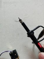 correctwaytomeasure.jpg150.9 KB · Views: 116
 -
 IRSOUTPUT.jpg272.9 KB · Views: 120
 -
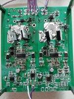 IRS.jpg408.1 KB · Views: 164
 -
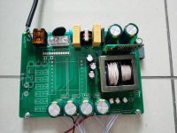 ACDC.jpg251.7 KB · Views: 158
 -
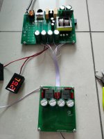 HU.jpg255.7 KB · Views: 157
Last edited:
Hi chchyong89
Your edges seem way to soft on the scope.
What Gate resistors are you using?
On you voltmeters you have around +-80V, but your Vpp is only 151V ... where do you lose almost +-5V in idle mode .... something must be wrong, I think
If Aliexpress Red ferrite 22uH, means a true type 2 coil, it should not get more than lukewarm .... I would be a little carefull buying coils off Aliexpress, eBay etc ....
Maybe if you share the schematics ...
/Baldin
I notice your probe is set to 1x mode, did you have it 10x mode for the measurement? in 1x mode its bandwidth is lower than 10x mode and will round the edges of waveforms.
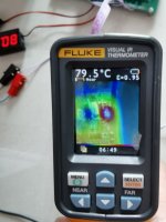
mission failed🙁🙁🙁 The smd version ran very hot even during idle.
Under +/-50V the inductors run not even warm, but once i push to +/-80V, the inductors run very hot even during idle. Tried with the blue color sendust too, but seems no different, its still running hot under +/-80V.
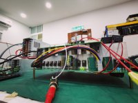
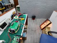
Just made another large heatsink version with 2 x irs2092 with 3 pairs irf640 each. managed to load 12pcs 100Vrms 100w light bulbs @ 1khz continuously, drawing power from a 24Vdc input DCDC LLC into +/-80V.
Thats around 50Amps on running on DC. 😀
Under +/-50V the inductors run not even warm, but once i push to +/-80V, the inductors run very hot even during idle. Tried with the blue color sendust too, but seems no different, its still running hot under +/-80V.
Just made another large heatsink version with 2 x irs2092 with 3 pairs irf640 each. managed to load 12pcs 100Vrms 100w light bulbs @ 1khz continuously, drawing power from a 24Vdc input DCDC LLC into +/-80V.
Thats around 50Amps on running on DC. 😀
Attachments
Last edited:
Sorry to hear that.
What exact type of coils are we talking about??
Size of the core?
Wire gauge?
What is the switching frequency?
What exact type of coils are we talking about??
Size of the core?
Wire gauge?
What is the switching frequency?
- Home
- Amplifiers
- Class D
- First time with BSC320N20NS3 G on IRS2092