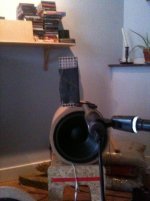
A small (but time consuming) test of a cirlce esl segmented in rings. loads of faults, next time i would triple check before i waste material and time.
i wanted to see if i could segment the rings, i know i got verry little surface area for the highes frequency's but since its for an active system i thought maybe it is possible to eq for it, so the balance is right and the dispersion increased. just a brain fart. so maybe its a shitty idea, since i got 5 rings and the middle one prety small, i can always use 4 rings if i cant compensate for the dB loss, ,
The PCb material is 0.5mm thick, and the stator frame is 6 mm HPL i cut away 1.6 mm to let glue the pcb in (like quad does) the HPL Is rather stiff so thats good, also it gives me some flesh to screw the final product in a baffle. also because the HPL is stiff the frame wont bent when aplying heavy stretched mylar.
Things i need to do right next time are (if its even useable) ,
solder tabs. i should have made some solfder tabs to solder the wires to 🙁
i know hope i can solder some small wires to it without clogging one of the holes and create s spot prone to arcing....
Not using holding tabs in the machining stage for the stator frame, since i dont want to clean the frames up next time i let the cnc drill some extra holes so i can screw the parts that fall out to the table. speaking about holes. the holes to screw the whole thing together dont line up. apparantly i was in a hurry to finish something so i f**** up. also i hate sketchup, really need to use an alternative its not accurate at all its screws allot of things up. rounding off distances so nothing alligns when flipped over for instance. aaargh
well at least my pcb stators looked pretty nice, all holes are drilled. 2 mm wide and are spaced 4 mm appart center to center, took the machine about 30 minutes total to create one stator. thats not even that bad. i can imaginge you stack a few of these pcb's only for the drilling step. 2 at one time would half the drilling from 25 to 12.5 or stack 4,reduces time to 6.12 minutes for one. (or bite more since every hole takes a bit longer now)
aah well some pictures, ill try and put some mylar on it tomorow, and buy some resistors.
Attachments
![IMG_2095[1].jpg](/community/data/attachments/429/429713-1795d7b8ef69c5a4d429cbe92e2e393f.jpg?hash=F5XXuO9pxa)
![IMG_2096[1].jpg](/community/data/attachments/429/429729-dc73a3fdf1d411d17c100476e4998153.jpg?hash=3HOj_fHUEd)
![IMG_2097[1].jpg](/community/data/attachments/429/429747-70e01e80b9c70f1c127d44050e2cb2d8.jpg?hash=cOAegLnHDx)
![IMG_2098[1].jpg](/community/data/attachments/429/429759-9d751c6a069a2aac1e69ed086252713f.jpg?hash=nXUcagaaKq)
![IMG_2099[1].jpg](/community/data/attachments/429/429770-7c365ae02dcbcf87e8416ee30c6bdf99.jpg?hash=fDZa4C3Lz4)
![IMG_2100[1].jpg](/community/data/attachments/429/429780-aa63a2f35e425c73095a1b48b5282648.jpg?hash=qmOi815CXH)
Last edited:
Congrats on your TWEESL!
Well thats something. i honestly did not see that page. my idea conceived (ofc first of all since i have Esl63) because i was making a Open baffle speaker, and wanted a round esl as well with wide dispersion 🙂 unlike you i wont be using delay lines, to much of a hassle if you ask me 🙂. i will read ur topic now 🙂 ,
I thought you were making headphones. 🙂
yeah big ones 🙂 well first tests. i am not liking what i hear. efficiency is incredible low. so low its not useable. also when using the resistor networkfor the different rings, it introduces some sort of noise. as in static noise. i am not sure what this is. its weird, my small panels play even louder then this, although this has 4 times the surface area. its not the coating since i can upp the voltage and the foil gets sucked into one of the stators. so HV is there on the menbrame. arg all that hard work for nothing 🙂
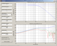
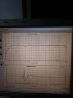
hmm i noticed some weird stuff, in the segmentation program.
When i use a . for sizes less then one meter the SPL goes up compared to 1 meter in hight.
that seems weird. when i use 05 instead of 0.5 i get again another result.
here are the pictures first 1 meter then 0.5 then 05 meter.
hmm doing something wrong ?
i thought the program was for horizontal dispersion
Attachments
Well made a rectangular version with just 2 segments, based on cheap 0.5 mm PCb i could get for 1 euro a piece (+- 22 cm x 28 cm)
reconfigured my cnc to work faster 🙂
https://youtu.be/vefvQRBSvnk
will assemble tomorow, and see if that works beter. still no clue why the circle failed on me
total time it takes for one stator is 7.35 min, way better then the 30 minutes on the circle 🙂 (also less holes)
reconfigured my cnc to work faster 🙂
https://youtu.be/vefvQRBSvnk
will assemble tomorow, and see if that works beter. still no clue why the circle failed on me
total time it takes for one stator is 7.35 min, way better then the 30 minutes on the circle 🙂 (also less holes)
Attachments
![IMG_2104[1].jpg](/community/data/attachments/433/433343-dc39069537e1bb31e8e1a075b5625773.jpg?hash=3DkGlTfhuz)
Last edited:
Solid carbide, 3.5 mm dia 2 flute. well i wont run it this fast in other material. but since i remove so little the bit can handle easy, and the tiny bit of flur at the edges i remove with a sandpaper. its especially the accelertation why it looks so fast, but cutting speed is around 4000 mm a minute. but high accelerations are the the time savers since all distances are pretty close together, so if you have a machine that can run 10000 mm a minutes it still has to get to that speed in a movement of only 4 mm 🙂 usually machines dont. allot of G forces are at work at these acelerations, i mean the ganrty is prety light but still 20-25 kilo. try to accelerate that to 10000mm a minute in a plit second. for me this is also the first time i run at this high speeds and accel. kinda scary , but it seems to do fine 🙂
The program is for horizontal dispersion, but calculations are based on assumption that the ESL panel behaves as a line source.When i use a . for sizes less then one meter the SPL goes up compared to 1 meter in hight. that seems weird. when i use 05 instead of 0.5 i get again another result.
here are the pictures first 1 meter then 0.5 then 05 meter. hmm doing something wrong ?
i thought the program was for horizontal dispersion
This was discussed over in the ESL simulator thread:
http://www.diyaudio.com/forums/plan...r-esl-simulator-esl_seg_ui-2.html#post2913884
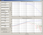
With this in mind, it makes sense that the SPL will be the same no matter what you enter for the length. What WILL change is the capacitance for each section. This is what is causing your responses to change differently than you expected. When you changed the length from 1m to 0.5m, you halved the capacitance. So the knee in the LP filter formed by the capacitance and 200K ladder resistance moves up in frequency by a factor of 2. If you adjust the ladder resistor to compensate, you will see that the response is still the same no matter what length you enter. Attached are re-runs of your simulations with adjusted R values. (BTW, entering 05 meters = 5 meters)
Now, a 0.5m ESL panel will not behave like a line source when measured/listened at 3m. Using the spreadsheet attached to the post linked above, you will find that it transitions to point source behavior for frequencies below 4kHz. So, the esl_seg_ui program output is really only valid above 4Khz for this combination of height and listening distance.
There is another ESL simulator available that is valid for all panel dimensions and listening distances.
You can add resistance in series with the panel, but it doesn’t support multiple segments.
Electrostatic Loudspeaker (ESL) Simulator
Some discussion of its use here:
http://www.diyaudio.com/forums/planars-exotics/258958-help-esl-simulator.html#post3988441
http://www.diyaudio.com/forums/planars-exotics/258958-help-esl-simulator.html#post3989632
I meant to add...very nice looking PCB stators

Attachments

Last edited:
yeah i do know this capacitance wil increase when entered 1 meter isntead of 0.5 🙂 dumb me , i somehow dis not think of re entering the resistor values to match the same dispersion, and ending up with ur graphs. Thanks Bolsert !!!
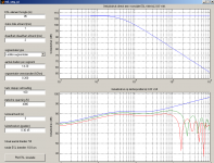
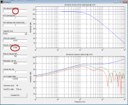
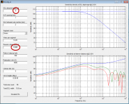
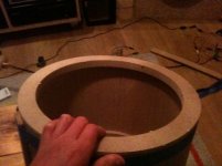
here i finished a test version , with some help from the minidsp it plays from 350 hetz to 20K, since the esl is baffles some extra shelving was required. the felt i used to dampen the resonance of the panel a bit, its around 200-250 hard to say exact because i used some supporting dots wich broaden the peak a bit. i used 48db oct filters to cross to a 12 inch woofer in open baffle (now in my circular baffle wich have a bit to long wings) since i use minidps as crossover and, the set is fully active with a TPA3116 based amplifier, i used some heavy Eq on the woofer to get rid of the insane huge humps caused by the tube resonance (i should have made the tube not this long so the resonance would be out of the pass band) although i almost did no eq ing to increase the low end for baffle roll off. here are some picutres of the contraption im playing around with and how i made it. (the fun part)
here some video's for the bending
https://youtu.be/H_wJCVRtVHw
https://youtu.be/NxAQnf86iX0
Oh yeah the graph of the frequency responce is made with holmimpulse and used smoothing 1/3 oct. bit to much to my taste , but all measurements where takenin room , pretty hard.
Attachments
Last edited:
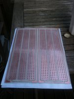
welll i made some rectangluar versions today 🙂 measures 272.5-96.5mm
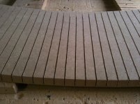
3 rows of copper of 25,25 mm 2 outer rows are connected to each other at the bottom, so when you sigment you dont have to ad another wire. the trace can be scrapet away to have 3 seperate rows. just ad some frame like plastic louvre and some foam spacers and you got one stator, for mid high frequency's res freq will be around 200-300Hz. there is no coating on the copper clad, but since my old quad ESl63 does not have a coating and is from the serial number 3000 , it seems not to be a huge problem. did not see any flashovers on them either.
i made like 28 of those , if someone would be interested just let me know, its an easy way, compared to all other methods to produce a a stator fast, you could also stack multiple in one stator frame. (glue on louvre panel)
picture is from 2 stators on one pcb not yet cut to size. (i get a guillotine cutter in 2 days) ill try to make a HPL stator frame tomorow to house them.
since the material is only 0.5 mm the pcbs do need a suport structure, like a louvre panel
Attachments
- Status
- Not open for further replies.
- Home
- Loudspeakers
- Planars & Exotics
- First time trying to use PCB material