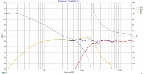
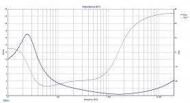
Hi guys, I am new to the forum and also my first time designing a crossover for a 2 way speaker. Done it using XSim and attached are the frequency responds and Impedance curve. Do the curves look alright or is there something needs to be corrected. Look forward to your comments.
Attachments
Last edited by a moderator:
One concern I have is that your impedance gets quite low, and typical amplifiers would have a problem with that.
Another smaller issue is that the slopes appear uneven. I can tell because phase comes and goes along with frequency. I'm not sure whether this will be a problem.
(* google drive doesn't seem to like other sites linking)
Another smaller issue is that the slopes appear uneven. I can tell because phase comes and goes along with frequency. I'm not sure whether this will be a problem.
(* google drive doesn't seem to like other sites linking)
There is a need to know more about the design. Namely the speakers used and the crossover circuit. Basically the low impedance is an indication of a serious problem as pointed out by Allen B.
Thank you for the comments. The low impedance also worried me a lot. After reading your comments, I went over my XO circuit again and found out that the low impedance is mainly caused by an inductor in the tweeter circuit. After adding some resistors to it, now it looks much better. Care to comment on the new impedance curve?
Btw I am using a Dayton Audio RS180P-8 7" Reference Paper Woofer 8 Ohm and a Peerless by Tymphany XT25BG60-04 1" Dual Ring Radiator Tweeter 4 Ohm. Is this combination good for listening to vocal and Jazz? Hopefully this combo does not sound too bright or harsh in the high region.
Before and After
Btw I am using a Dayton Audio RS180P-8 7" Reference Paper Woofer 8 Ohm and a Peerless by Tymphany XT25BG60-04 1" Dual Ring Radiator Tweeter 4 Ohm. Is this combination good for listening to vocal and Jazz? Hopefully this combo does not sound too bright or harsh in the high region.
Before and After
An externally hosted image should be here but it was not working when we last tested it.
An externally hosted image should be here but it was not working when we last tested it.
Show us a Frequency Response plot where you remove the system phase, but instead display the phase of each driver.
At 1.5 kHz, your woofer response is several dB higher than your system response... this makes me suspect that your tweeter is partially cancelling your woofer in this region. It is true that this can result in a flat system frequency response, it is also true that it may not sound good. It is better if the woofer and tweeter are in phase with each other at the crossover frequency, and each is down by about 6 dB... then they just add together nicely.
Good job so far on your first attempt.
Let me try again,
An externally hosted image should be here but it was not working when we last tested it.
An externally hosted image should be here but it was not working when we last tested it.
 Google image drives don't link here well. But you can right click on the link to go to the image.
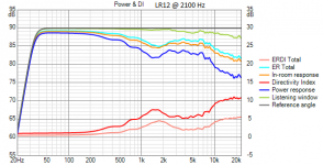
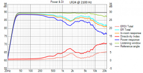
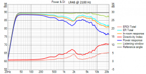
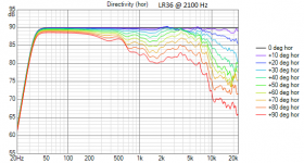
Show us also power response, off-axis polarmap -180...+180 deg hor & ver, listening window rms, early reflections rms and estimated in-room response.
Show us also power response, off-axis polarmap -180...+180 deg hor & ver, listening window rms, early reflections rms and estimated in-room response.
Uh, he did say politely, first time at this 😉
Hi guys, I am new to the forum and also my first time designing a crossover for a 2 way speaker. Done it using XSim and attached are the frequency responds and Impedance curve. Do the curves look alright or is there something needs to be corrected. Look forward to your comments.
The on-axis SPL curve looks okay, but that does not mean the design will sound good. You'll need to consider the off-axis SPL curves in order to check if the dispersion and power response is right, which is needed to learn anything about "how it will sound".
Apart from this, it would be useful to tell us more about the design overall, the drivers, and show the x-over circuit. Just attach the images to your post (don't link to external files).
You'll need to consider the off-axis SPL curves in order to check if the dispersion and power response is right, which is needed to learn anything about "how it will sound".
The above is true... however...
He is crossing a 7 inch driver to a 1 inch tweeter at about 2100 Hz. That fact by itself will pretty much determine the horizontal off-axis performance. If he gets the on-axis response right, the off-axis response will be acceptable.
This is the first time, and he is off to a good start. Lets help him get the on-axis response right. Then we can focus on cabinet edge diffraction and baffle step effects, and help him make any adjustments necessary.
I highly recommend you read this before spending anymore time simulating:
Simulated Measurements - undefinition. Lot's of good information on how to avoid the pitfalls of simulating without valid data.
Simulated Measurements - undefinition. Lot's of good information on how to avoid the pitfalls of simulating without valid data.
He is crossing a 7 inch driver to a 1 inch tweeter at about 2100 Hz. That fact by itself will pretty much determine the horizontal off-axis performance. If he gets the on-axis response right, the off-axis response will be acceptable.
'Acceptable' is just personal decision and could mean anything. Maybe 'right' on-axis does not equal to flat...
Off-axis performance depends also on box shape/diffraction, location of drivers, crossover slopes and phase matching. Typically off-axis performance of 7"+1" (w/o wave guide) could be okay with straight axial response and phase match on-axis when acoustical slopes are not steeper than 2nd order.
Few examples with 6.5" woofer and 1" tweeter. Box size and shape are not optimized specially for this driver combination and XO frequency so none is acceptable with flat axial imo. Acoustical 2nd order is the smoothest, but flat on-axis produce dip due to exact phase match at XO.
Attachments

The horizontal off-axis will be acceptable, but what about the vertical?He is crossing a 7 inch driver to a 1 inch tweeter at about 2100 Hz. That fact by itself will pretty much determine the horizontal off-axis performance. If he gets the on-axis response right, the off-axis response will be acceptable.
If you look at the OP's frequency response plots, the drivers are only summing to about +2dB at the crossover point, so the phase alignment is somewhere more than 90 degrees out of phase. The result of this is that there is (worst case) a +4dB peak aimed towards the roof, and a null aimed towards the floor or vice versa. In a real world room, this means that the on axis response is no longer flat, as the reflected peak will probably still be heard. A link-witz riley alignment (0 degrees / in phase) means that only nulls can be produced vertically off axis, which are far less audible than peaks.
Another way to avoid this problem is to make sure the drivers are placed less than 1/4 wavelength centre-to-centre on the baffle, making the radiation close to omnidirectional at the crossover frequency. This equates to 4cm at 2.1kHz, an impossibility with a 7" woofer. Even if you satisfy this placement criteria, the drivers aren't summed together as efficiently as they would if they were phase aligned, therefore they are each being driven louder than necessary at the crossover frequency, increasing non-linear distortion.
OP: post the crossover schematic and we can work out what is causing the impedance to drop so low.
Last edited:
Uh, he did say politely, first time at this 😉
Beginners do not cause frustration. Quasi experienced designers who show bad example and recommend their own limited perspective, methods and tools do that. Starting with the basics does not mean that methods and tools should be limited keeping as many users on diyaudio in the Middle Ages as possible.
I should not mind this because I design commercial speakers only, but somehow I do 😕 Too big part of me is still diy.
The first set of pictures show a severe phase response anomaly around crossover. You want both drivers to show smooth rolloff in the crossover region, instead one driver is clearly rising. The flat axial response curve is not sufficient to illustrate the problem with the crossover. You will need to look at individual and combined phase response as well.
We ideally also need info on the drivers for a slightly more informed reply. There are a number of other considerations, such as time-alignment and impedance. Impedance is clearly a problem with the speaker, it's an amp-killer.
We ideally also need info on the drivers for a slightly more informed reply. There are a number of other considerations, such as time-alignment and impedance. Impedance is clearly a problem with the speaker, it's an amp-killer.
The crossover design that James Tan requires is crucial to being able to match a tweeter with a 4 ohm nominal impedance to a woofer that corresponds to an 8 ohm rating. He needs to supply the circuit diagram that he has used so far. All speaker systems represent a good deal of compromise and all that can be achieved is to be able to get the best out of the components used without going to unnecessary expense. Does anyone have the zma file for the Dayton RS 180P-8 as I am unable to download it from the Dayton Audio site?
- Home
- Loudspeakers
- Multi-Way
- First time designing crossover, comments needed