I have wanted a 300b SET for a long time. After considering many different driver ideas, I came up with the following KISS design. I am a newbie at tubes and I won't take claim for any creativity or being too original. I enjoyed the sound of the 12b4 preamp so much I figured if I could get a grounded cathode driver to swing close to 70V with a 2V input I should try it. I thought about using a CCS for the cathode resistor but held back for the first effort. Maybe try it later.
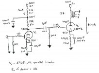
For this circuit B+ is 500V using a 3k primary with the bias set to 80mA on the 300b. The driver is a 5965 with the triode paralleled. This is decoupled from the output stage by a dropping resistor of 3k bypassed to ground with a 20uF GQ cap. The resulting voltage across the drive circuit is 450V. Ra = 14k resulting in a plate voltage of 222V at idle. With a 2V input it will swing 68V at an Zo of 3k. The bias of the driver is 16mA across the plates using a bypassed 270R resistor. Any thoughts or comments for an improvement in this design. Better yet will it work????
P.S. Filaments are regulated DC. Forgive the hand drawn schematic, I don't have any fancy software to do it yet.
Attachments
I'm slowly coming up to speed on some sort of high-ish power (10-15 W would be nice) SET amplifier myself. I'm currently looking at the 300B and have run a couple of quick sims with it.
The 300B is limited to 400 V on the anode. Granted, there are some types out there that claim to be able to handle up to 450 V, but from what I understand, they're highly unreliable when operated at that high voltage and tend to go into thermal run-away. I would limit B+ to 400 V. Also, I think with that high voltage and the 3 kOhm impedance of your OPT, you'll be quite a ways off the sweet spot of the 300B's. You'll maybe get a little more headroom, but you'll be trading off THD in a big way. At least that would be my concern. Also, if you want max power out of the 300B, your driver circuit should probably have lower output impedance as you'll be driving the 300B a bit into class A2. Many people add a cathode follower between the input stage and the 300B - or do what George (tubelab) does in the TubelabSE and add a source follower.
I suggest throwing the circuit into a SPICE (or the like) circuit simulator. I use PSpice 9.1 Student Edition which can be downloaded here. You can get models for a handful of tubes - including the 300B - on Norman Koren's site.
Good luck! Keep us posted.
~Tom
I thought that my plate voltage on the 300B was pushing it. Per SE Cad it would be right at its limit of 400V. Easy enough to change the load and voltage. A 3.5k would be more useful if I don't like this design. Given a 3.5 k I could push up idle current to 90mA with B+450V which would put plate voltage to 350ish.
I was not intending to operate into class A2. However, I guess a good question would be what is an "acceptable" level of Zo for the driver stage? I actually thought that 3k was pretty good for A1. Unless I missed something (which I am sure I did) it should drive >>20kHz
I have downloaded pspice. Will take a while to figure that out. I am still pretty much at the stage of getting tubecad to work and drawing loadlines on paper.
I have a tubelab SE sitting in front of me. (minus xfmrs). However, in this circuit I didn't want to put in SS.
The learning curve on spice can be a bit steep at first. But it's worth it.
Just remember that transient simulations are versus time, AC sims are versus frequency. So for distortion simulations, you'd want to run a transient simulation at the frequency of interest and figure the THD from the harmonics (it's set up as part of the transient sim).
Thankfully, spice is reasonably well documented and there are tons of tutorials available on the net.
~Tom
Redeign using CF
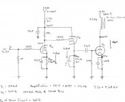
Although I have not put this in PSpice, I thought it worthwhile, based on comments, to redesgn the driver with a CF using the 5965 tube. In this case I split the triode, one for gain and one for buffer. This drops the Zo of the driver to 165ohm. Total gain of the amplifier is 34.08 which is still within my goal. I am not opposed to other tubes or using two tubes for the circuit. I just have a few of the 5965 laying around.
I also dropped 300b current to 70mA at 350V plate. This reduced bias voltage to 70v. At full input now the driver has to get closer to 0 volts on the 300b grid. At that point I am not sure if there is enough current flowing through the CF to drive the 300b properly. At this time I still want to avoid A2 operation.
The other question I have with a CF do you or do you not want to bypass the cathode (Rkb) resistor?
Attachments
If you want to stay within Class A1 why don't you use the recommended operating conditions by WE?
For example: 400V/60mA, bias -87V. If you choose a 5Kohm : 8ohm transformer you will get 8.3W (a little less in practice because of the transformer loss) with 3% 2nd harmonic, 0.5% 3rd harmonic and much less for higher harmonics. That's 3.05% THD approx.
If the load of your speaker drops to 5.6 ohm the primary load will be 3.5K and you will get for the same input (174 V peak-to-peak) 10.5 W with 5% 2nd harmonic, 1.2% 3rd harmonic etc. (approx. 5.2% THD).
Practically you could use any nominal 8 ohm speaker.
If the driver is a triode that can swing 61.5 Vrms with dominant 2nd harmonic you could get lower overall THD in a wide frequency band because of harmonic cancellation.
Cheers,
45
The other question I have with a CF do you or do you not want to bypass the cathode (Rkb) resistor?
That resistor should not be bypassed. Your 20uF power supply cap presents a zero impedance to AC at the plate. If you installed the bypass capacitor, you would also have a zero impedance to AC at the cathode. Both plate and cathode are now shorted to circuit common. No more signal.
My sense is that putting a 300B in this sort of topology is a little like cramming a Porsche engine in a Pinto. There is a lot you can do to improve things -- CCS plate and cathode loads, LED bias, Power Drive, Ultra-Path cap, Shunt regulators, DRD, etc. -- and without some of that you won't reap the benefit of an expensive DHT. Might still sound better than a KT88 or whatnot, but it won't sound as good as it can.
Further, the filament supply and the power supply are probably more critical here than things like whether you use a cathode follower or not, and they should not be after thoughts.
Finally, 4.7u is a little large for the coupling cap. 0.22u, or even 0.1u, would be fine with the 200K resistor.
Further, the filament supply and the power supply are probably more critical here than things like whether you use a cathode follower or not, and they should not be after thoughts.
Finally, 4.7u is a little large for the coupling cap. 0.22u, or even 0.1u, would be fine with the 200K resistor.
I can understand wanting to build an amplifier that is sand free. However if you are going to use a cathode follower you are basically back to the Tubelab SE topology. I would argue that the FET follower would do a better job than the tube. Additionally you could go back to your first schematic and use an active FET load and take the signal from the Mu output to get an equally low output impedance as the follower.
I am also wondering why you want to avoid A2 but don't use recommended points? At 350vp you should be around 50mA to 60mA @ -76 to -74 with that load. Of course this can vary per tube, but the recommended points are usually a good place to start.
Additionally you could try transformer coupled with fixed bias. It would cost a bit more, but it is an elegant solution to lose everything in the signal but a couple resistors, a couple transformers, and the tubes of course. You could also look to try a tube with lots of balls so that it can drive the output if/when it starts to pull grid current without the follower, something like the 6BQ5, D3a, or 12HG7. I posted an idea a-la Gary Pimm using the 6BQ5 CCS loaded, however you wouldn't need to CCS load it, simple resistors would also work. Take special note in Pimm's test of the 90V out @ .25% distortion figure. This type of circuit could, and would, drive the living snot out of the 300B at any of the 350vp operating points.
As mentioned above, DRD could be an excellent option for avoiding sand. With DRD you are back to two stage instead of three....two with a follower; and you would lose almost all of the junk in between.

James
I am also wondering why you want to avoid A2 but don't use recommended points? At 350vp you should be around 50mA to 60mA @ -76 to -74 with that load. Of course this can vary per tube, but the recommended points are usually a good place to start.
Additionally you could try transformer coupled with fixed bias. It would cost a bit more, but it is an elegant solution to lose everything in the signal but a couple resistors, a couple transformers, and the tubes of course. You could also look to try a tube with lots of balls so that it can drive the output if/when it starts to pull grid current without the follower, something like the 6BQ5, D3a, or 12HG7. I posted an idea a-la Gary Pimm using the 6BQ5 CCS loaded, however you wouldn't need to CCS load it, simple resistors would also work. Take special note in Pimm's test of the 90V out @ .25% distortion figure. This type of circuit could, and would, drive the living snot out of the 300B at any of the 350vp operating points.
As mentioned above, DRD could be an excellent option for avoiding sand. With DRD you are back to two stage instead of three....two with a follower; and you would lose almost all of the junk in between.
James
Attachments
I was not intending to operate into class A2. However, I guess a good question would be what is an "acceptable" level of Zo for the driver stage? I actually thought that 3k was pretty good for A1. Unless I missed something (which I am sure I did) it should drive >>20kHz
Unless you're feeding it some simple waveform, operate into Class A2 you shall. Music programs have fast rising transients that can be way above the average value, and these will likely drive the grid positive. These DHTs also tend to pull grid current even before the grid actually swings positive. Finally, 300Bs need adequate grid drive. Most of the complaints about disappointing sonic performance are due to inadequate grid drive. For any DHT, the MOSFET source follower is just about the closest to ideal grid driver, even if you operate Class A1 most of the time. A decent grid driver will handle overdrive more gracefully, and not contribute to sonic degredation. There is no lack of current sourcing, and the Zo is much lower than anything hollow state can give (since MOSFETs have much higher gm's than any vacuum tube).
However, in this circuit I didn't want to put in SS.
I'd use the SS. If you are dead set against that, then consider using an interstage xfmr (and be prepared to spend some $$$$ for a good one, cheap IT's are a major sonic compromise) and connect it to a stiff driver like a 12B4, trioded 6V6, 6AQ5, 6BQ5, or the low-u section of those dissimilar dual triodes that were used as vertical deflection oscillator/finals. That's just about the best hollow state way to deliver grid drive to a DHT.
Thanks,
I think it is important to understand what the aim is. This amp is to be my building block of understanding for the nuances of tube audio. Start with KISS (Keep It Simple Scott) and build complexity refinements in later once I understand what is going on. I will have two designs to immediatley compare it to. Tubelab Simple SE (not sure what tube yet) and a Tubelab SE which will be runnning 300b's as well. Hopefully at some point in the near future I can contribute to this community more than I suck away from it. Thank you very much for your help so far.
Thanks zigzagflux, I didn't think it should be bypassed but wasn't 100% sure. Your explination make perfect sense.
dsavitsk. Don't pick on Pinto's, they are cars of my era. (That and Disco). You are right, in its current design it won't be ultimate. Thats okay for today and will give me something to do tommorrow. Although not yet in good enough form to present yet, the P.S. and heater circuits will not be insignificant. I will probably use silicon in the heater circuits to obtain the goals. I'll post them shortly. And yes coupling cap is too large. For the present I will just put in 0.47uF until final output stage design is completed.
As far as the 300b operating point, my suggested operating points are based on being a newbie and using SE Cad. While I considered the recomended operating points by W.E. they were all less than 3.5k @ 350V plate to get any kind of power output.
Initially was trying to get power, then to balance power vs. THD. Maybe SECad isn't the tool I should use as it flags the 5.0k and 4.0k primaries as too high of an impedance. THD calculations do agree with above comments.
Attached is a load line curve were I bumped up Vplate to about 395v using a 4.0k primary. From my inexperienced perspective, this looks good. I am driving the tube to 80% of its max power, producing 10.1W with 2.5% 2nd and 0.3% 3rd order harmonics. Vin is +/-66 V. There is quite a bit of headroom before hitting A2. At the limit of A1 it is showing close to 15W with 3.3%2nd and .3%3rd. I know I must be missing something in this process so please help me. I probably will have the OPT made by Electraprint, so we can make it pretty much anything. This is an area where I want to get right so I am all ears.
Miles, As I am learning I am opening up to the use of mosfets. I certainly like my alephs. I have plenty of 12b4's laying around and am quite happy with their sound at this point as well. After running kids around tonight I will read-up on those ideas as well and try to come up with a circuit.
My ultimate goal is to have my system tri-amped. Using SE for Upper and Mids which are are 93 and 91 db/watt and and PP for the lower as it is only 89db. I don't need or want to blow the windows out. I know really good h.e. fullrange and horns exist, but I have never been exposed to them other than what I read on the boards.
Attachments
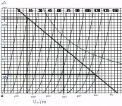
Attached is a load line curve were I bumped up Vplate to about 395v using a 4.0k primary. From my inexperienced perspective, this looks good. I am driving the tube to 80% of its max power, producing 10.1W with 2.5% 2nd and 0.3% 3rd order harmonics. Vin is +/-66 V.
From the picture, with +/-66V it looks like you get approx. 5.5W. Rather poor efficiency. You get 10W with +/- 82V input.
The original WE recommended loads for 350V/60mA are 4K, 3K, 2K. If you go for 4K you get 7W (THD is a bit more than 3%), if the load from your speaker drops at 6 or 4 ohms the primary impedances will be 3 and 2K respectively. The Pout for 2K is more than 10W. I don't think you can find more info for other tubes.
Cheers,
45
Last edited:
Thanks 45, Calculated by hand and your right 5.5W. I came up with 5.8W before transformer loss. Went back to SECad and found the I had not checked RMS out. I checked it and the results came back at 5.18W with the transformer I used.
Proves the danger of sims in that they are only as good as those who operate it. Unless you can determine what is reasonable, then something as simple as a check box will throw everything off.
I am now back to Standard operating points, designing for better A2 operation, and hand calculating.
Thanks Again
After looking at a FET follower, the complexity involved in setting up a negative power supply violates my KISS at this point. I will get to hear that design with the tubelab SE. I am sure it sounds great.
Back to simplicity, the interstage xfmr.
Is the Lundahl 1660 @ 1:2.25 considered to be a "good" interstage? Another possibility would be to have Electraprint wind one. Don't hear much about his stuff however. Another one I saw was a Sowter @1:1.
I guess if I go this route then a DRD should be considered. I am far away from my original concept at this point but oh well.
Huh? It is true you will hear it with the Tubelab SE so it may be moot, but all it takes is a couple of diodes and a cap or two.the complexity involved in setting up a negative power supply
All three of the listed transformer companies make top notch iron. You may not hear to much about Electra-Print because people are to busy listening 😛 As a bonus Jack is one of the nicest people I have chatted with. The inter-stage with fixed bias is just about as simple as it gets, DRD is right up there with it. Here is something to chew on a bit, keep in mind that it uses an all out cost-no-object power supply. You could take it another step even and lose the R/C on the driver cathode, replacing it with an LED.
http://www.users.globalnet.co.uk/~valveamp/images/SE108IT2.GIF
James
Agreed 200% !Miles Prower said:. . .
Music programs have fast rising transients that can be way above the average value, and these will likely drive the grid positive . . .
Using a cathode follower (or source follower) is a good way to recover quickly after an overload if, and only if it is DC coupled to the 300B grid.
And to do so, you'll inevitably have to stack some negative and positive supplies.
If the link cap remains, you loose all the profit !
In short, problems arise when this link cap receive charging current thru the direct biased diode constitued by the G1 to K in the 300B.
This shifts bias wich recover slowly while the cap discharges thru grid leak resistor.
Yves.
Last edited:
I retract my statement of complexity after looking at SJS schema. My first impression of negative supply is from tubelab SE, which when boiled down is equally as simple in concept.
I was hoping Jack at electraprint made a good interstage. He was good to deal with although he would only talk through email. I don't have much data on his IT so I will use the LL1660 as a reference for the time being.
The SJS uses a 1:1 IT so it will require a driver tube with a mu greater than 30 in my case. I have plenty of gain in my pre to drive the amp. What is an equiv to a 437A?
If the IT has a ratio 1:2.25 (LL1660 T) I can use a lower mu tube, possibly with higher bias current. This would raise the impedance driving the 300b, which I would assume ( hate to use that word but in this case a good choice ;-) ) compresses the dynamics by reducing the grid recovery. My basis for this statement is that the grid current would have to fight secondary impedance and not the DCR. The secondary DCR remains the same for the both cases using a LL1660.
I will post a schema later for your consideration. Again I would like to thank everyone that has contributed so far. This has been a great learning experience.
I would prefer the LL1671/30mA. With 3K source and open secondary you get 30Hz-30KHz +/-1dB which is very good for a SE. The ratio is 1:1, the inductance 35H. The max output at 30Hz is 130 Vrms!
Using a 1:2.25 step-up the driver will see a capacitive load 5 times higher.
Could be used with a triode-strapped 6F6GT (which is a bit better than the 6V6 in this application) if you want just a slight swing (few volts) into positive grid.
If you want more drive you could go for a 45 which is more linear with lower loads.
For example, at 240V/30 mA you can get 200V P-P into 4K, i.e. 1.2W, with 3% THD approx.
The input stage can be a good medium/high gain triode.
Using a CF will NOT add anything to the sonic quality - more like worsen it greatly.
A 300B is not hard to drive, use a decent tube like a 6H30 and run it at a lot of current (say 20mA) and you'll get all the drive you need, and a far simplier signal path.
Regards, Allen (Vacuum State)
A 300B is not hard to drive, use a decent tube like a 6H30 and run it at a lot of current (say 20mA) and you'll get all the drive you need, and a far simplier signal path.
Regards, Allen (Vacuum State)
P.S.
Don't worry about that 3% THD from the 45 it is practically 2nd harmonic only at 200V P-P into 4K!
The curves of the 45 and 300B are extremely similar in terms of linearity and very likely you get the best condition for perfect harmonic cancellation. That is, you get low overall THD from your amp if the input triode has very low distortion!
- Status
- Not open for further replies.
- Home
- Amplifiers
- Tubes / Valves
- First 300b Design, Please comment