I would like to change a design using through hole components to SMD components, but how do I find equivalent SMD transistors?
The transistors used in the original design are: 2N5401, 2N5551, 2SD669 and 2SB649.
The transistors used in the original design are: 2N5401, 2N5551, 2SD669 and 2SB649.
Hi
You might be able so find something here: http://www.repairfaq.org/REPAIR/F_SMD_trans.html
or here
http://info.electronicwerkstatt.de/bereiche/bauteile/smd/smd_aktiv/
\Jens
You might be able so find something here: http://www.repairfaq.org/REPAIR/F_SMD_trans.html
or here
http://info.electronicwerkstatt.de/bereiche/bauteile/smd/smd_aktiv/
\Jens
sounds like a Slone amplifier to me --
1/4 watt resistors are usually 1206 or 1210
1/2 watt resistors are 2010
1 watt resistors are 2512 --
if you have to use larger resistors consider the TO-220 mounts -- these take up very little space
the 1n4148's can be surface mount as well -- you could use a SOT-23 version -- MMBT4148 -- or the MMBT4148SE which is two diodes ! or the MMSD4148 which is SOD-123.
The transistors -- MMBT5401 and MMBT5551 -- remember that the current mirrors should be matched pairs.
The 2SD669, 2SB649 -- you might be able to use the MJD340 and MJD350 -- these are DPAK (On Semi) -- if you do use these I have heat sinks for DPAK devices --
Thanks! I found 5+ alternative parts for the 2N5401 and 2N5551 using this link.JensRasmussen said:
Do you have any experience with this site? I'm just wondering if the parts listed are equivalent or only similar.
Yes, it's Sloan's headphone amp, opamp version, from his project book.jackinnj said:sounds like a Slone amplifier to me --
1/4 watt resistors are usually 1206 or 1210
1/2 watt resistors are 2010
1 watt resistors are 2512 --
if you have to use larger resistors consider the TO-220 mounts -- these take up very little space
the 1n4148's can be surface mount as well -- you could use a SOT-23 version -- MMBT4148 -- or the MMBT4148SE which is two diodes ! or the MMSD4148 which is SOD-123.
The transistors -- MMBT5401 and MMBT5551 -- remember that the current mirrors should be matched pairs.
The 2SD669, 2SB649 -- you might be able to use the MJD340 and MJD350 -- these are DPAK (On Semi) -- if you do use these I have heat sinks for DPAK devices --
I was thinking about these parts:
- BC components MMA0204 resistors, 1/4W, MELF package (1206 compatible package)
- Tantalum and ceramic capacitors
- BAS32 diodes (I got some of these and they're supposed to be 1N4148 equivalent.)
- AD797 opamp, SOIC package
At the moment I'm considering making a layout with both SMD and through hole mount for the transistors, just in case.
Thanks for your help 🙂
Brannigan said:
At the moment I'm considering making a layout with both SMD and through hole mount for the transistors, just in case.
Thanks for your help 🙂
Once you start doing surface mount you'll dread going back to "through-hole".
The site which you posted looks helpful.
I don’t have any experience with that particular site, I just found I while searching with Google.
Reengineering a circuit is quite like engineering a new circuit. You need to look through a lot of datasheets and compare data on new devices with the original. Be sure to make the first version of your PCB in a way that makes it possible to try different alternative components, as you probably won’t be able to find the ideal substitute from datasheets alone.
I agree that SMT has several advantages over through hole, but SMT requires a whole new stock of components, so for the DIY people that need to be considered as well.
Good luck with your project, and please keep us updated with your progress.
\Jens
JensRasmussen said:I don’t have any experience with that particular site, I just found I while searching with Google.
Reengineering a circuit is quite like engineering a new circuit. You need to look through a lot of datasheets and compare data on new devices with the original. Be sure to make the first version of your PCB in a way that makes it possible to try different alternative components, as you probably won’t be able to find the ideal substitute from datasheets alone.
I agree that SMT has several advantages over through hole, but SMT requires a whole new stock of components, so for the DIY people that need to be considered as well.
Good luck with your project, and please keep us updated with your progress.
\Jens
Jens -- smt devices are much cheaper than through-hole
you are absolutely correct in proto-ing the PCB -- this is especially true in switch-mode power supplies where a few millimeters of trace add nano-henries -- a lot of impedance given the switching speeds.
JensRasmussen said:Reengineering a circuit is quite like engineering a new circuit. You need to look through a lot of datasheets and compare data on new devices with the original. Be sure to make the first version of your PCB in a way that makes it possible to try different alternative components, as you probably won’t be able to find the ideal substitute from datasheets alone.
I'm hoping I can just replace the through hole components with SMD equivalents and it will work. Maybe I'm too optimistic. 🙂
JensRasmussen said:Good luck with your project, and please keep us updated with your progress.
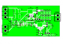
Sure. I've finished the layout and it might be sent to the boardhouse tomorrow.
The boardlayout is for:
- 1206 resistors
- Tantalum and 0805 ceramic caps
- MMSD4148 diodes
- MMBT5401/MMBT5551 or 2N5401/2N5551 transistors
- MJD340/MJD350 or 2SD669/2SB649 transistors
Attachments
If you are going to use the AD797 OpAmp -- you should take a careful look at Analog's website --
http://www.analog.com/UploadedFiles/Data_Sheets/507345751AD797_d.pdf
there are some tricks to using the AD797 which they discuss -- see figures 34 and 35 in the datasheet. basically they involve bypassing the feedback resistor to keep the noise in the nanovolt region. it's a matter of picofarads ! I bring this up because it was part of the Super-Regulator thread (the Jung superregs used the AD797, AD825 etc.) there is also a distortion cancellation mechanism -- see figure 41.
also -- Q3 and Q4 (referring to the part numbers in "The Audiophile's Project Sourcebook) operate in Class A -- I don't know whether the somewhat lower-rated OnSemi devices are going to do -- when you first brought the topic up I thought you were using the devices in the VA stage. Not to worry, however, there are many DPAK devices which will handle the current.
I didn't read the AD797 datasheet initially, since I thought Sloan had considered it. Anyway, I've read through it, but there's plenty I don't understand.
I'll do these modifications:
- add cap between AD797 pin 8 and ground
- add resistor and cap in series in parallel with R5 (Sloan's schematic)
I don't know what values I'll use for the new components, so I might need help with that later. 🙂
I'll do these modifications:
- add cap between AD797 pin 8 and ground
- add resistor and cap in series in parallel with R5 (Sloan's schematic)
I don't know what values I'll use for the new components, so I might need help with that later. 🙂
looking at the schematic, one thing which puzzles me -- why in fact use such a high-performance opamp and then couple the non-inverting inputs to the power supply rails via the protection diodes D1 and D2. If these diodes aren't matched then you will have an offset problem with the amplifier -- and the problem is exacerbated with temperature -- further, any noise on the supply rails is fed directly into the non-inverting input.
just my 2-pfennigs worth. i hope it's not getting overly complex.
just my 2-pfennigs worth. i hope it's not getting overly complex.
This might be a little above my skill level, but that's how you learn, right?
I haven't thought about a power supply yet. First, let's see if I get the amp working. 😉
I haven't thought about a power supply yet. First, let's see if I get the amp working. 😉

Tantalums are expensive, suggest to use MLC as a substitute. MLC are more reliable.
SMT cheaper than SMT?, not always the case, a 1N4148 diode in a DO-35 is usually cheaper than the SOD123 eqivalent, 1N4148-W. It comes down to volumes, in many cases. Good luck with your design. BTW can you post the schematic for us that do not have teh project book, Thanks Rick
SMT cheaper than SMT?, not always the case, a 1N4148 diode in a DO-35 is usually cheaper than the SOD123 eqivalent, 1N4148-W. It comes down to volumes, in many cases. Good luck with your design. BTW can you post the schematic for us that do not have teh project book, Thanks Rick
Advice to an eight year old thread? That project will be gathering dust or is something else now. The guy may not even be around. 😀
Tantalums are expensive, suggest to use MLC as a substitute. MLC are more reliable.
SMT cheaper than SMT?, not always the case, a 1N4148 diode in a DO-35 is usually cheaper than the SOD123 eqivalent, 1N4148-W. It comes down to volumes, in many cases. Good luck with your design. BTW can you post the schematic for us that do not have teh project book, Thanks Rick
What value and where are the tang caps used? If large and used for input coupling best case would be a NP elec bypassed with a ceramic NP0 cap in the 100nF range.
Ian, yes you are correct, 8 years old thread, I must have been sleepy and did not look at the dates, funny how, @Boscoe also replied as well. Info none the less if someone reads it, Oh well at least we got your attention 🙂
Thanks
Rick
Thanks
Rick

- Status
- Not open for further replies.
- Home
- Amplifiers
- Solid State
- Finding SMD equivalents of through hole transistors