Hi, I plan to use the following transformer setup:

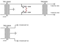
The diagram bellow shows a 'regular' hum balancer wiring.
In this case there must be galvanic connection between the fillament windings and ground.
R-drop resistors are needed to drop from ~9v AC to ~6.3v
R11-12/ 21-22 are chosen 1k so that it has neglibile effect when it shortens the transformer winding (leftmost), and the R-DROP.
There are seporate R-drop and hum balance wiring for two identical tubes - this is for symetrical load distribution between the two transformers.
The HT transformer is connected that way as well - to share load from both primary transformers.
But would it actually work?
As far as I understood, the hum balancer shifts the fillament AC phase, so it kind of cancels out relative to the tubes power supply.
Here the balancer is connected to ground and the fillament potential 'starts' ~3 volts above the ground.
// R-drop should be ~8.1 ohm, R fillament is supposed to be ~18 ohm
There could be other options for wiring, I allready got confused drawing this one 🙂
Next option is regulated DC power supply, so the rectifier kind of 'isolates' the fillament ground from the common ground.
Least favourable is adding seporate heater transformer.
In general I want to keep it as simple as possible with the layout above.
Regards - Emil
Last edited:
No it doesn’t. It gives a balanced impedance to ground from both filament rails. This causes the opposite phases in the twisted filament wiring to cancel better.the hum balancer shifts the fillament AC phase
This way
And what the impedance should be?
The 'ordinary' hum balancer have a mid impedance of 250 ohms (R500 trim-pot) and it worked in a circuit I made. Don't know if it is optimal though.
- one side of the filaments would have low impedance: R-drop || 1k to R-drop || (1k + R-trim), about ~8 ohms
- the other side is higher: 1k to 1k + R-trim
And what the impedance should be?
The 'ordinary' hum balancer have a mid impedance of 250 ohms (R500 trim-pot) and it worked in a circuit I made. Don't know if it is optimal though.
So in case of regulated power supply would there be a benefit of trim-pot balancer?
And how well it will be isolated from the transformers ground through the bridge rectifier and regulator?
The application is a relatively high gain guitar amp, 2 x 6n2p/ ecc83 tubes.
And how well it will be isolated from the transformers ground through the bridge rectifier and regulator?
The application is a relatively high gain guitar amp, 2 x 6n2p/ ecc83 tubes.
Still haven't started on the project, but I think there should be some benefit from the trim-pot with DC filament as well.
The balance pot creates two opposite voltages with respect to the ground.
The ripple in the two halves is opposite and cancels out.
If it works with AC it should also work with DC.
Don't know if one can hear a difference when the filament voltage is already rectified and the residual ripple is small.

As simple as requiring a different power transformer.Keep it simple
Filament is 6.3v, transformer is 2x9v.
P.s. Is there a benefit to balance each tube individually? It is a gainy guitar amp.
So it might get as simple as ...two regulated power supplies (extra parts but better transformer load and heat dissipation balancing) + option for individual trim-pot balancer for each tube..
P.s. Is there a benefit to balance each tube individually? It is a gainy guitar amp.
So it might get as simple as ...two regulated power supplies (extra parts but better transformer load and heat dissipation balancing) + option for individual trim-pot balancer for each tube..
What tubes will you be using? Most tubes don’t need DC heating; proper twisted AC wiring should be enough.
If you have to use DC, it’s only needed for the driver, not for the final tubes.
Regards, Gerrit
If you have to use DC, it’s only needed for the driver, not for the final tubes.
Regards, Gerrit
In which case putting the heaters in series won’t work.I left the transformers in your diagram unchanged
Why, what valves are you planning to use? (I was assuming voltage doublers for the +/-18V btw)putting the heaters in series won’t work.
Last edited:
All valves are 6.3v.
I will experiment with total of 2 preamp tubes for 3-4 gain stages.
If I passively drop the voltage from 18vAC to 12.6v (tubes in series), how am I going to employ the trim-pot balancer?
Across the two filaments in series?
Note that ef86 have lower filament current, ecf80/82 higher than 6n2p.
I might also drop-in 1 piece 6n1p (pin compatible with 6n2p) for a lower gain, but it has almost twice the current of 6n2p.
So it would require to adjusting the drop resistors to get the filament voltages in range (hopefully). But they won't be equal.
I will experiment with total of 2 preamp tubes for 3-4 gain stages.
- ef86/6j32p, 6k4p + 6n2p
- 6n2p + 6n2p
- ecf80/82 + 6n2p
If I passively drop the voltage from 18vAC to 12.6v (tubes in series), how am I going to employ the trim-pot balancer?
Across the two filaments in series?
Note that ef86 have lower filament current, ecf80/82 higher than 6n2p.
I might also drop-in 1 piece 6n1p (pin compatible with 6n2p) for a lower gain, but it has almost twice the current of 6n2p.
So it would require to adjusting the drop resistors to get the filament voltages in range (hopefully). But they won't be equal.
You don't need to 🤷♂️how am I going to employ the trim-pot balancer?
To be honest, I hardly hear any effect of the setting of a humdinger pot when using indirectly heated tubes. Two 100R resistors from each phase to make an artificial center tap (or a real CT as with your transformers) to ground (or a bit elevated) and you're fine.
Just make sure the wires are tightly twisted and properly routed.
If you're mixing different tube types, don't put them in series.
Just make sure the wires are tightly twisted and properly routed.
If you're mixing different tube types, don't put them in series.
No they aren’t. Big rectifiers are 5V. 300Bs are 5V. Other filament voltages exist.All valves are 6.3v.
(or a bit elevated) and you're fine.
I much prefer elegant simplicity. I don't really get the three power transformers and involved schematic just to minimize some filament hum.
From what I understand, the main cause of filament hum in indirectly heated tubes is that the cathode is sitting at a positive voltage w/r/t the filament, and act as a plate gathering electrons boiling off the hot filament. I really like how Dave Gillespie handled this in this Maggie 8600 redesign:
"HEATER BIAS: The two 100 ohm resistors connected between the heater terminals and ground at the output tube socket closest to the power transformer should both be disconnected from the ground lug they were connected to (which will now have nothing connect to it), and then connected to pin #3 of the same tube socket. This will provide about 5.7 vdc of bias for the heater winding to help minimize any hum generated across the heater/cathode elements within the AF amplifier tube."
Elevating the floating heater circuit to cathode voltage makes a lot of sense to me, and just using the "old" method of two same-value resistors. How much additional complication do you have to throw at a problem that really is not a problem?
I have a 1 tube hybrid amp and the trim-pot balancer definitely works.
I was pulling hair to figure why suddenly there was annoying buzz (after taking the tube module out an mounting it back) - it was that I swapped the AC wires for the filament...
Swapping it back or readjusting the trim-pot fixes it. 2x100R might just do the same, but I suspect that the filament itself is not perfectly 'balanced' with the cathode or whatever.
P.s. 3 transformers setup is because It is a lot cheaper than custom ordered transformer, especially if you already have some
So in the 3 transformers layout I could elevate the already connected to ground side of the filament?Elevating the floating heater circuit to cathode voltage makes a lot of sense to me, and just using the "old" method of two same-value resistors. How much additional complication do you have to throw at a problem that really is not a problem?
I can't make proper 2 sided elevation, cause of the transformers layout (tried in the circuits above).
But the one side 'elevation' must be about the voltage drop needed: 9 - 6.3 = 2.7v.
And we don't know if this is the most proper voltage for a minimum hum.
But I can use two different tubes with R-drop changed accordingly.
Last edited:
- Home
- Amplifiers
- Tubes / Valves
- fillament hum balancer trimpot