When hand wiring a chassis and especially wiring the heaters of the used tubes in an amplifier design, I am aware of the “how to’s” (twisting them for instance).
But when one wants to design an amplifier on a PCB you cannot “twist” those filament wires.
Are there some “how to’s“ to pay attention to on this particular subject to get thing done correctly?
I do not have much experience designing an amplifier using a PCB.
Tips are most welcome!
But when one wants to design an amplifier on a PCB you cannot “twist” those filament wires.
Are there some “how to’s“ to pay attention to on this particular subject to get thing done correctly?
I do not have much experience designing an amplifier using a PCB.
Tips are most welcome!
Yes. Just cut the heater traces at the tube socket pin and hard wire the heaters with twisted cable, lift it away from the PCB as much as practical.. Easy and much better.
when one wants to design an amplifier on a PCB you cannot “twist” those filament wires.
The filament wiring can be a twisted pair off-board.
Or run them close together on the same side of the pcb.
Or run one on top of the pcb, and the other on the bottom, directly below.
In any event, keep the filament wiring well away from grids and input circuitry.
You can make an actual twisted pair on a PCB. It takes a 4 (or more) layer board to do it. Just put the twisted pair(s) on the other side of a ground plane. Along with any digital control stuff or other ‘dirty’ circuitry you might add. You could on theory do it with just a 2 layer, but they will be guaranteed to get in the way of everything else so they really need their own layers.
I just run the heaters on tracks but keep them away from audio level signals, especially the input low level audio. I keep the input audio tracks as short as possible.
I haven't had any problems with hum.
I haven't had any problems with hum.
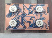
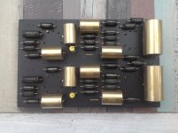
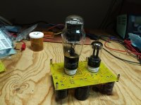
I never put tube sockets on PCBs, it is unreliable. Tube sockets must breathe, so I connect them by flexible wires to PCBs.
The sockets I buy from Cricklewood Electronics have quite long leads on them so there is room for expansion and contraction.
You can get some compensation of magnetic fields by making two loops with opposite directions using three tracks: F1-F2-F1.
Thanks forum members for your responses. Much appreciated!
@Hanze Khronye:
"Yes. Just cut the heater traces at the tube socket pin and hard wire the heaters with twisted cable, lift it away from the PCB as much as practical.. Easy and much better."
I will consider that if heater wiring turns out to be too complicated on my pcb design.
@rayma:
"Or run one on top of the pcb, and the other on the bottom, directly below."
I think, because I will use a two layer pbc, will certainly look at this possibility.
@wg_ski"
"You can make an actual twisted pair on a PCB. It takes a 4 (or more) layer board to do it."
For me the pcb then will be far too expensive.
@Wavebourn:
"I never put tube sockets on PCBs, it is unreliable. Tube sockets must breathe, so I connect them by flexible wires to PCBs."
Can you supply a photograph of this solution please? Will be very interesting for me.
@nigelwright7557:
"The sockets I buy from Cricklewood Electronics have quite long leads on them so there is room for expansion and contraction."
Did a visit to that site but could not discover what kind of sockets you mean.
@MarcelvdG:
"You can get some compensation of magnetic fields by making two loops with opposite directions using three tracks: F1-F2-F1."
I think I understand what you mean: Suppose three tubes
then connect from filament supply : f1(T1) to f2(T2) to f1(T3) and back f2(T3) to f1(T2) to f2(T1) back to filament supply?
Jeeez, what a lot of vias and so connections between first and second connections layers. But the idea is clear to me. How did you manage to do this? I am using Fritzing as PCB design software.
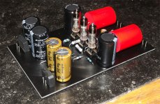
I have build a lot of tube pcb's. Never had problems with heater supply on pcb.When hand wiring a chassis and especially wiring the heaters of the used tubes in an amplifier design, I am aware of the “how to’s” (twisting them for instance).
But when one wants to design an amplifier on a PCB you cannot “twist” those filament wires.
Are there some “how to’s“ to pay attention to on this particular subject to get thing done correctly?
I do not have much experience designing an amplifier using a PCB.
Tips are most welcome!
Just use DC heater supply at sensitive amps like phonoamp and with linelevel or poweramps single side pcb AC heater supply never a problem.
Attachments

Last edited:
"I have build a lot of tube pcb's. Never had problems with heater supply on pcb.
Just use DC heater supply at sensitive amps like phonoamp and with linelevel or poweramps
single side pcb AC heater supply never a problem."
Well, that never occurred to me as a possibility, but is worthwhile considering!
Only it needs extra circuitry to get that done in stead of a simple extra transformer heater output.
@Wavebourn:
"I never put tube sockets on PCBs, it is unreliable. Tube sockets must breathe, so I connect them by flexible wires to PCBs."
Can you supply a photograph of this solution please? Will be very interesting for me.
Attachments
Thanks Wavebourn for sharing your picture. I now understand that the tubes are not part of the pcb but mounted sideways of separate pcb parts and hand wired.
That is of course an option also.
That is of course an option also.
@MarcelvdG:
"You can get some compensation of magnetic fields by making two loops with opposite directions using three tracks: F1-F2-F1."
I think I understand what you mean: Suppose three tubes
then connect from filament supply : f1(T1) to f2(T2) to f1(T3) and back f2(T3) to f1(T2) to f2(T1) back to filament supply?
That may be a good idea, but it is not what I meant 😉
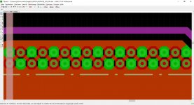
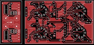
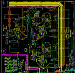
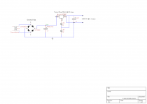
Attached are two layout plots of a valve DAC I made some time ago. The total heater current is about 2.7 A, so I made relatively wide traces around the right and top part of the PCB with an F1-F2-F1 layout. The magnetic field of the left loop (F1-F2) is supposed to cancel the magnetic field of the right loop (F2-F1).
I tap off these big wires at various places and do the hook-up from there to the adjacent valve sockets with simple narrow traces placed close to each other to keep the loop area small (although at some places there is a trimmer potentiometer in the way). It's a pity that there is no cancellation of fields exactly where the wires are the closest to the valves, but then again, twisted wires in a chassis-built circuit also usually miss a few twists right next to the valves.
Attachments


I have build a lot of tube pcb's. Never had problems with heater supply on pcb.
Just use DC heater supply at sensitive amps like phonoamp and with linelevel or poweramps single side pcb AC heater supply never a problem.
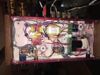
I've built 4 with PCB's so far. And with traces on the board for heaters I go DC as well and have had zero hum problems. The board I'm using now has eyelets right next to the pins on the socket for the heaters. So AC with twisted pairs should be ok to use. Some of these new boards are pretty well thought out. The one I'm using this time can be tweaked for kt77, 6v6, 6l6 or el34 tubes. It also has schematics for several power supplies using SS or tube rectifiers.
- Status
- Not open for further replies.
- Home
- Amplifiers
- Tubes / Valves
- filament wiring tube heaters on pcb's