Does anyone remember this topology discussed here? I did a search and could find no info. I am interested in how this sounds compared to CCS on the cathode and floating filament supply. Is there a lot of noise from the current passing through the cathode resistor?
The 12,5V must be coming from a CCS. I have shown the same topology (with CCS) in the "26 preamp thread" but not built it yet.
Yes, great thread! Thank you Lars. No bypass cap needed is very good. This could also work well with IDH tubes, cathode tied to the top of the bias resistor on the heater.
Last edited:
The first person I ever recall utilizing such a setup was Thomas Meyer about 15 years ago...but, if I remember correctly, there was no CCS, just an L-C-L-C-L filter.
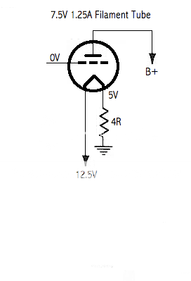
Such a setup works well, but can generate a lot of heat! Probably most practical with DHTs that have low filament current draw, like the 112A.
Jim
Such a setup works well, but can generate a lot of heat! Probably most practical with DHTs that have low filament current draw, like the 112A.
Jim
Last edited:
Thank you Jim,
Ha ha, that WOULD be a lot of heat for something like a GM70 😉 Even with 7.5 V filament at 1.5A a 15W part would get mighty hot. Do you remember what tubes Thomas was using? I am surprised this is not used much more often. I think it would be great for the input tube of a phono-stage for instance where the typical bypass capacitor on the cathode bias resistor is so audible. Or where the graininess of LED bias is evident.
Hope you are well.
I believe Thomas was biasing WE 101Ds (or maybe it was 101Fs) in this manner.
My 'still-under-construction-after-about-a-year-and-a-half' phono project biases the 12BZ7 (V1) this way.
Jim
My 'still-under-construction-after-about-a-year-and-a-half' phono project biases the 12BZ7 (V1) this way.
Jim
Instead of a big heat dissipating resistor, why not use another tube ? For example two 6.3 V tubes in series, 12.6 VDC supply. One tube has 0 - 6.3 Vdc, average "bias" 3.15 V, the other has 6.3 - 12.6 Vdc across it, average bias 9.45 V.
Robert, yes using the filament of tubes for bias is another good idea. Remember, on DHT, bias measurement is always taken from the more negative voltage cathode pin. On IDH tubes connect the cathode to the positive side of the heater. There is no 'average' bias. A 12.6v supply feeding two series tubes with 6.3v heaters, that have the same current draw, would have bias voltages of 6.3v and 12.6v respectively.
Last edited:
I think this topology was used in some WW2 German radio station. Single system tubes.
I saw it in old military RX too.
I saw it in old military RX too.
I think this topology was used in some WW2 German radio station. Single system tubes.
I saw it in old military RX too.
Yah - I figured there was an earlier use of this approach - there always seems to be 🙂
If you have more info, I'd be curious to know what tubes this was used with back in the good ol' days...as I indicated earlier, heat becomes a major consideration with this approach.
Jim
FWIW, I can see this bias style being useful in combination with the 6SC7 and its single cathode connection for both sections. A 5 Ω Caddock MP915 looks tough enough to take the power dissipation, without a heatsink, and it will be quiet.
Does anyone remember this topology discussed here? I did a search and could find no info.
Is this the thread you are looking for? http://www.diyaudio.com/forums/tubes-valves/147199-dht-bias-filament-supply-one.html
- Status
- Not open for further replies.
- Home
- Amplifiers
- Tubes / Valves
- Filament current bias